Table of Contents
Advertisement
Available languages
Available languages
Betriebs- und Serviceanleitung
Reparaturanleitung
Frischölgeschmierte Drehschieber-Vakuumpumpen
- 1 -
V-VWZ
V-VWZ 102
V-VWZ 162
V-VWZ 252
V-VWZ 402
B 117
1.4.99
Gardner Denver
Schopfheim GmbH
Postfach 1260
79642 SCHOPFHEIM
GERMANY
Fon +49 7622 / 392 - 0
Fax +49 7622 / 392 - 300
e-mail: er.de@
gardnerdenver.com
www.gd-elmorietschle.com
Advertisement
Chapters
Table of Contents

Related Manuals for Gardner Denver Elmo Rietschle V-VWZ Series


Summary of Contents for Gardner Denver Elmo Rietschle V-VWZ Series
- Page 1 V-VWZ Frischölgeschmierte Drehschieber-Vakuumpumpen V-VWZ 102 V-VWZ 162 V-VWZ 252 V-VWZ 402 B 117 1.4.99 Gardner Denver Schopfheim GmbH Postfach 1260 79642 SCHOPFHEIM GERMANY Fon +49 7622 / 392 - 0 Fax +49 7622 / 392 - 300 e-mail: er.de@ gardnerdenver.com www.gd-elmorietschle.com...
-
Page 2: Table Of Contents
Inhaltsverzeichnis Seite Betriebs- und Service anleitung VWZ 102 – VWZ 402 Allgemein Eignung Ausführungen und Aufbau Ausführungen Aufbau Datenblätter und Ersatzteillisten Mögliches Zubehör Typische Anwendungsgebiete Arbeitsweise Pumpe Überströmventil Ölschmierung Abdichtungen Installation Mechanische Installation 5.1.1 Aufstellung 5.1.2 Saugseite 5.1.3 Abluftseite Elektrische Installation 5.2.1 Allgemein 5.2.2... -
Page 3: Allgemein
ETRIEBS ERVICE ANLEITUNG 1. Allgemein Alle Pumpen, die aus irgendwel- chen Gründen (z.B. Wartung) an uns zurückgeschickt werden, müssen von Schad- und Giftstoffen frei sein. Eine entsprechende Bescheinigung ist vorzulegen! Ex-Schutz-Sicherheitsvorkehrungen für Gesamt-Anlagen in welchen Vakuumpum- pen eingesetzt werden, sind kundenseits zu überprüfen und zu installieren. -
Page 4: Aufbau
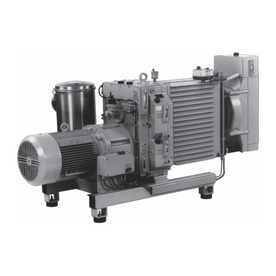
3.2 Aufbau (Bild 3 und 4) Die VWZ besteht aus der Getriebe-Einheit (Y ), den Anschlusseinheiten (S ), der Ölversorgung (L bis L ), dem Kühlsystem (R, ) und den Abscheidesystemen (Z, J ) auf der Saug- und Auspuff-Seite (Zubehör). Die Pumpen sind wassergekühlt. Ein eingebautes Überströmventil (Q) gewährleistet das Einschalten und Betreiben der Pumpe in jedem Druckbereich. -
Page 5: Datenblätter Und Ersatzteillisten
3.3 Datenblätter und Ersatzteillisten siehe folgende Datenblätter: ➝ VWZ 102 – VWZ 402 (14) D 111 Durchlaufkühlung ➝ VWZ 102 – VWZ 402 (13) D 117 Umlaufkühlung siehe folgende Ersatzteillisten: E 117/1 Teile der Grundeinheiten E 117/2 Antrieb und Getriebeeinheit E 117/3 Umlaufkühlung E 117/4... -
Page 6: Arbeitsweise
4. Arbeitsweise 4.1 Pumpe Die Verdichtereinheiten der VWZ arbeiten nach dem Drehschieberprinzip und sind frischölgeschmiert. Ihre Förder richtung ist von oben nach unten. Deshalb fallen z.B. mitangesaugte Verunreinigungen oder Kondensate nach unten und können leicht abgeführt werden. 4.2 Überströmventil Zwischen der HD- und ND-Stufe befi ndet sich ein Überströmventil, das federbelastet ist. Dieses Überströmventil hat dabei folgende Funktion: Beim Einschalten der Pumpe bei atmosphärischem Druck öffnet dieses Ventil auf Grund des entstehenden Überdruckes zwischen ND- und HD-Stufe. -
Page 7: Elektrische Installation
5.2 Elektrische Installation 5.2.1 Allgemein (siehe Datenblätter D 111 + D 117) Die elektrischen Motordaten sind auf dem Datenschild (N) bzw. dem Motordatenschild angegeben. Die Motoren entsprechen DIN / VDE 0530 und sind in Schutzart IP 54 und Isolationsklasse B oder F ausgeführt. Das entsprechende Anschlussschema befi ndet sich im Klemmenkasten des Motors. - Page 8 6. Betrieb 6.1 Kühlfüssigkeit 6.1.1 Durchlaufkühlung (Bild 12) Für die Inbetriebnahme der Pumpe (VWZ 102 – VWZ 402 (14)) wird zuerst die Wasserleitung am Schlauch- anschluss (C) angeschlossen. Durch Eindrücken der Ventilkappe bis zum Anschlag des Selbstschluss- Durchgangsventil (U ) fl ießt Wasser in das Kühlerge- häuse (Y ).
-
Page 9: Ölschmierung
6.2 Ölschmierung (siehe Datenblätter D 111 + D 117) Ölschmierpumpe Die Pumpe wird mit gefüllten Ölvorratsbehältern (ausgenommen Frischöl) Weniger Öl Mehr Öl versandt. Trotzdem sollten aus Sicherheitsgründen die Ölstände überprüft werden. Voller Füllstand ist jeweils erreicht, wenn sich der Ölspiegel im oberen Drittel des Ölstandsanzeigers befi... -
Page 10: Störungsbehebung
7.2 Ölnebelabscheider (Zubehör Abluftseite) Die Ölnebenabscheider werden direkt an den Ausblas- fl ansch der Vakuumpumpe angefl anscht. Die Abscheidung erfolgt immer in zwei Stufen: Abscheidung: ➞ Flüssigkeitsteilchen im Kondensat sammelraum ➞ Aerosole in den Filterkerzen Die Ölnebelabscheider sind für die chemisch-pharmazeu- tische Industrie in zwei Materialvarianten verfügbar: ➞... -
Page 11: Demontage Der Verdichterstufen
EPARATURANLEITUNG 1. Demontage und Montage des Kühlergehäuses (Bild 12, 13 und Datenblätter D 111 + D 117) • VWZ abschalten und auf Atmosphärendruck fl uten. • Öffnen der Verschlussschraube (U ) bzw. • Ablassen der Kühlfl üssigkeit: - VWZ (14) ➝ am Ablasshahn (K - VWZ (13) ➝... -
Page 12: Wechsel Der Kupplungsgummi Und Der Kupplungsbolzen
4. Wechsel der Kupplungsgummis und der Kupplungsbolzen 4.1 Am Antrieb (Bild 22 und 23) • Demontage und Montage des Antriebs (siehe Seite 12). • Sicherungsring (38) lösen und Kupplungsgummi (37) abziehen und ge- gebenenfalls auswechseln. • Sicherungsring (87) lösen. • Kupplungshälfte (G ) mit einer Abziehvorrichtung von der Antriebswelle (72) abziehen. -
Page 13: Montage Der Lagerteile Und Dichtungen
5.2 Montage der Lagerteile und Dichtungen (Bild 26) • Vor dem Zusammenbau sind alle Teile aus der Lagerbohrung des Gehäusedeckels (25) bzw. (55) zu entfernen. Die Teile (Pos. 10, 11, 12, 13, 14, 15, 17, 23) überprüfen und eventuell auswechseln. •... -
Page 14: Wechsel Der Lamellen
6. Wechsel der Lamellen (Bild 27) • Demontage des Kühlergehäuses und der B-Seite der Verdichterstufe (siehe Seite 12 und 13). • Lamellen (S ) herausnehmen und überprü- fen. • Achtung! Falls notwendig Lamellen nur satzweise wechseln. • Lamellen in Rotorschlitze einlegen (ange- schrägte Fläche der Lamellen muss mit dem Rotorradius übereinstimmen. - Page 15 7.2 Montage der Lagerteile und Dichtungen (Bild 28 und 29) • Vor dem Zusammenbau sind alle Teile aus der Lagerbohrung des Gehäusedeckels (25) bzw. (55) zu entfernen. Die Teile (Pos. 10, 11, 12, 13, 14, 15, 16) überprüfen und eventuell auswechseln. •...
-
Page 16: Reparaturen Am Getriebe
8. Reparaturen am Getriebe 8.1 Demontage und Montage des Getriebegehäuses (Bild 30 und 31) • Öl ablassen: (siehe Datenbläter D 111 + D 117). - Frischöl an (K) / Lageröl : HD an (K ) und ND an (K - Getriebeöl an (K •... -
Page 17: Demontage Und Montage Des Getriebegehäuses
8.3 Wechsel der Lager, Wellendichtringe und Dichtungen im Anschlussgehäuse (Bild 33) • Demontage und Montage des Kühlergehäu- ses und der Verdichterstufen (siehe Seite 12). • Demontage und Montage des Getriebege- häuses (siehe Seite 17). • Lösen der Sicherungsringe (87) an der Antriebswelle (72) und an der Stirnradwelle (74). - Page 18 Fresh oil lubricated rotary vane vacuum pumps V-VWZ 102 V-VWZ 162 V-VWZ 252 V-VWZ 402 BE 117 1.4.99 Gardner Denver Schopfheim GmbH Postfach 1260 79642 SCHOPFHEIM GERMANY Fon +49 7622 / 392 - 0 Fax +49 7622 / 392 - 300 e-mail: er.de@...
- Page 19 Contents Page Instruction and service manual VWZ 102 – VWZ 402 Introduction Application Variations and Construction Variations Construction Data sheets and spare parts lists Accessories Typical Field of Application Method of Operation Pump Pressure Relief Valve Oil Lubrication Shaft Seals Installation Mechanical Installation 5.1.1...
-
Page 20: Introduction
NSTRUCTION AND SERVICE MANUAL 1. Introduction In the event of a pump being re- turned to us, for whatever reason (eg.repair) it must be free of all danger- ous and toxic material. A corrosponding certifi cate has to be presented! Explosion proof standards for the plant in which the vacuum pump will be installed, are the responsibility of the customer and... -
Page 21: Construction
3.2 Construction (fi g. 3 and 4) VWZ pumps are constructed in fi ve main sections, i.e. gear box (Y ), compression stages (S ), oil supply (L to L ), cooling system (R, Y ) and separator systems (Z, J ) on the suction side and exhaust side (optional). -
Page 22: Data Sheets And Spare Parts Lists
3.3 Data sheets and spare parts lists see following data sheets: ➝ D 111 / DA 111 (USA) External cooling VWZ 102 – VWZ 402 (14) ➝ D 117 / DA 117 (USA) Circulation cooling VWZ 102 – VWZ 402 (13) see following spare parts lists: E 117/1 Parts for fundamental Units... -
Page 23: Method Of Operation
4. Method of operations 4.1 Pump The compressor unit of the VWZ is a fresh oil, once through lubricated, rotary vane type pump. The fl ow direction is from top to bottom, so that any contamination in the suction stream or condensate is readily discharged. 4.2 Pressure relief valve The spring loaded pressure relief valve is located between the LP and HP stages. -
Page 24: Electrical Installation
5.2 Electrical Installation 5.2.1 General (see data sheets D 111 + D 117) The electrical data can be found on the data plate (N) or the motor data plate. The motors correspond to DIN / VDE 0530 and have IP 54 protection and insulation class B or F. The connection diagram can be found in the terminal box on the motor. Check the electrical data of the motor and the control gear for compatibility with your available supply (voltage, frequency, permissible current etc.). -
Page 25: Normal Operation
6. Normal Operation 6.1 Cooling Liquid 6.1.1 Fresh or External Cooling (fi g. 12) For starting-up the pump (VWZ 102 - VWZ 402 (14)) fi rst the water supply has to be connected to the hose connection point (C). The water jacket (Y ) is fi... -
Page 26: Oil Lubrication
6.2 Oil Lubrication (see data sheets D 111 + D 117) Oil metering pump The pumps are despatched with the oil tanks (except fresh oil) fi lled. However Reduction of oil Increase of oil it is advisable to check the oil levels. Sight glass: Fresh oil (I), LP-bearing (I ), HP-bearing (I ), gearbox (I... -
Page 27: Oil Mist Separator
7.2 Oil Mist Separator (Optional Extra Exhaust Side) The oil mist separator which is mounted directly on the exhaust fl ange of the vacuum pump is a 2-stage device: Separation: ➞ liquid droplets in the condensate collector ➞ aerosol in the fi lter elements The oil mist separators are available in 2 material variations for the chemical and pharmaceutical industries: ➞... -
Page 28: Removal And Reassembly Of Water Jacket
EPAIR NSTRUCTIONS 1. Removal and Re-assembly of Water Jacket (fi g. 12, 13 and data sheets D 111 + D 117) • Switch off VWZ and vent to atmospheric pressure • Open plug (U ) or (U • Drain off cooling liquid: - VWZ (14) ➝... -
Page 29: Removal And Reassembly Of Drive
4. Changing Coupling Rubbers and Pins 4.1 On Drive Motor (fi g. 22 and 23) • Removal and reassembly of drive (see page 12). • Remove circlips (38) and pull off coupling rubbers (37), replace if neces- sary. • Remove circlips (87). •... -
Page 30: Reassembly Of Bearings And Seals
5.2 Reassembly of Bearings and Seals (fi g. 26) • Before reassembly all parts should be removed from the end cover (25) or (55). Check parts (Pos. 10, 11, 12, 13, 14, 15, 17, 23) and if necessary replace. • Fit new oil seal (10) with assembly device (W ) into end cover (sealing lip see fi... -
Page 31: Changing Blades
6. Changing Blades (fi g. 27) • Removal of water jacket and non-drive end B of compressor stage (see page 12 and 13) • Withdraw blades (S ) and examine. • Important! If required, replace blades only in sets. • Insert blades in rotor slots (the bevelled side of the blades have to be at the rotor surface). -
Page 32: Reassembly Of Bearings And Seals
7.2 Re-assembly of Bearings and Seals (see fi g. 28 and 29) • Before re-assembly all parts should be removed from the end cover (25) or (55). Check parts (Pos. 10, 11, 12, 13, 14, 15, 16) and if necessary replace. •... -
Page 33: Repairs To Gearbox
8. Repairs to Gearbox 8.1 Removal and Re-assembly of Gearbox (fi g. 30 and 31) • Drain oil (see data sheets D 111 + D 117). - Fresh oil at (K) / Bearing oil LP at (K ) and HP at (K - Gearbox oil at (K •... -
Page 34: Changing Bearings, Shaft Seals And Seals
8.3 Changing Bearings, Shaft Seals and Seals in Gearbox Connection housing (fi g. 33). • Removal and re-assembly of water jacket and compressor stage (see page 12). • Removal and re-assembly of gearbox (see page 17). • Remove the circlip (87) on the drive shaft (72) and on the gear shaft (74).
Need help?
Do you have a question about the Elmo Rietschle V-VWZ Series and is the answer not in the manual?
Questions and answers