Advertisement
Quick Links
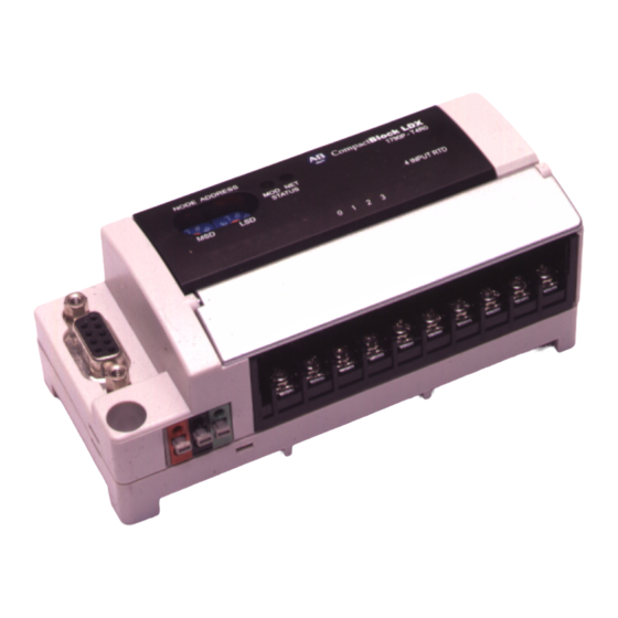
PROFIBUS DP Digital Base Terminal
Block CompactBlock LDX I/O
(Cat. Nos. 1790P-T8BV8V, -T8BV8B, -T0W6)
What This Document Describes
This document describes how to install your PROFIBUS DP
CompactBlock LDX I/O.
For information on:
GSD File Requirements
Important User Information
Installing CompactBlock LDX I/O
Wiring the Terminal Blocks
Wiring the PROFIBUS Connector
Troubleshooting
Specifications
GSD File Requirements
Current functionality of PROFIBUS DP CompactBlock LDX I/O
blocks requires GSD files.
These files are easy to install and are available online at:
www.ab.com/networks/gsd/
1PRE
Installation Instructions
Refer to page:
below
2
5
9
10
12
13
Publication 1790-IN009B-EN-P - April 2003
Advertisement

Subscribe to Our Youtube Channel
Related Manuals for Rockwell Automation Allen-Bradley 1790P-T8BV8V


Summary of Contents for Rockwell Automation Allen-Bradley 1790P-T8BV8V
- Page 1 Installation Instructions PROFIBUS DP Digital Base Terminal Block CompactBlock LDX I/O (Cat. Nos. 1790P-T8BV8V, -T8BV8B, -T0W6) What This Document Describes This document describes how to install your PROFIBUS DP CompactBlock LDX I/O. For information on: Refer to page: GSD File Requirements below Important User Information Installing CompactBlock LDX I/O...
- Page 2 In no event will Rockwell Automation be responsible or liable for indirect or consequential damage resulting from the use or application of these products.
- Page 3 Identifies information about practices or WARNING circumstances that can cause an explosion in a hazardous environment, which may lead to personal injury or death, property damage, or economic loss. Identifies information about practices or ATTENTION circumstances that can lead to personal injury or death, property damage, or economic loss.
- Page 4 Environment and Enclosure This equipment is intended for use in a Pollution Degree 2 industrial environment, in overvoltage Category II applications (as defined in IEC publication 60664-1), at altitudes up to 2000 meters without derating. This equipment is considered Group 1, Class A industrial equipment according to IEC/CISPR Publication 11.
- Page 5 Installing CompactBlock LDX I/O Follow these steps to install the base block: 1. Set the station address on the base block. 2. Mount the base block. 3. Mount the optional expansion blocks. 4. Wire the terminal blocks. 5. Connect the PROFIBUS connector. 6.
- Page 6 Mount the Base Block You can mount the base block to a panel or DIN rail. We recommend that you ground the panel or DIN rail before mounting the base block. When used in a Class I, Division 2, hazardous WARNING location, this equipment must be mounted in a suitable enclosure with the proper wiring...
- Page 7 Replace the base block on the panel and place a screw through each of the two mounting holes. Tighten the screws until the base block is firmly in place. 109.5 mm 4.3 in Expansion 42.5 mm Cover 1.7 in DIN Rail Mounting 1.
- Page 8 Mount the Optional Expansion Blocks The analog base blocks can accommodate a IMPORTANT maximum of two discrete expansion blocks. The RTD and thermocouple base blocks do not support any expansion blocks. Mount the expansion block by connecting it to a previously-installed CompactBlock LDX I/O base or expansion block.
- Page 9 Wire the Terminal Block The following figures show the wiring information for the terminal blocks. 1790P-T8BV8V Input/Output Base Block Wiring Diagram OUT0 OUT4 OUT2 OUT6 OUT1 OUT5 OUT3 OUT7 • Sinking inputs - wire COM (pin 9) to Field Power (-) GND Sourcing inputs - wire COM (pin 9) to Field Power (+) 24V dc Note: both COM (pins 9 and 10) are internally connected.
- Page 10 Wire and Connect the PROFIBUS DP Terminal Connector Follow these procedures when connecting the PROFIBUS DP terminal connector to the base block. If you connect or disconnect the PROFIBUS WARNING cable with power applied to this module or any device on the network, an electrical arc can occur.
- Page 11 Once you have properly wired the connector, attach it to the base block as shown below. Use the locking screws on the connector to fasten it to the base block. Module Power Connector (underneath module) PROFIBUS Connector Green - GND Black - COM Red - +24Vdc Connect Power to the Block...
- Page 12 Troubleshoot with the Indicators The base block has the following indicators: • module status • network status • I/O status Mod/Net Status Indicator LED Indicator: Status: Description: Module Status Solid Red Unrecoverable fault in base block Flashing Red Unrecoverable fault in expansion unit Solid Green Normal operation - OK No power...
- Page 13 PROFIBUS DP Digital Base Terminal Block Specifications The following table contains specifications that are common to all of the base blocks in this document. Individual base block specifications are detailed after this table. Environmental Specifications Operating Temperature 0 to 55°C (32 to 131°F) IEC 60068-2-1 (Test Ad, Operating Cold), IEC 60068-2-2 (Test Bd, Operating Dry Heat), IEC 60068-2-14 (Test Nb, Operating Thermal Shock)
- Page 14 PROFIBUS DP Specifications Network Protocol PROFIBUS-DP (EN50170) • Communication of the slave with a Class 1 master • Communication of the slave with a Class 2 master Redundancy Not supported Repeater Control RS485 signal Signal Implementation Type DPC31 Freeze Mode Supported Sync Mode Supported...
-
Page 15: Input Specifications
DC Input/Output Combination Base Block Specifications 1790P-T8BV8V, -T8BV8B INPUT SPECIFICATIONS Inputs per base block 8 points non-isolated, sinking or sourcing On-state voltage 9.6V dc minimum 24V dc nominal 28.8V dc maximum On-state current 8mA maximum per point @ 28.8V dc Off-state voltage 5V dc maximum 4.8K Ω... - Page 16 General Specifications PROFIBUS Power Supply voltage - 24V dc nominal Voltage range - 19.2-28.8V dc Power dissipation - 1.2W maximum @ 28.8V dc Field Power Supply voltage - 24V dc nominal Voltage range - 10-28.8V dc Power dissipation - 3.22W @ 28.8V dc Isolation I/O to logic: photocoupler isolation Isolation voltage: 1250V ac rms...
- Page 17 General Specifications PROFIBUS Power Supply voltage - 24V dc nominal Voltage range - 19.2-28.8V dc Power dissipation - 1.2W maximum @ 28.8V dc Field Power Supply voltage - 24V dc nominal Voltage range - 19.2-28.8V dc Power dissipation - 1.7W @ 28.8V dc Isolation I/O to logic: photocoupler isolation Isolation voltage: 1250V ac rms...
-
Page 18: Explosion Hazard
Allen-Bradley and CompactBlock LDX are trademarks of Rockwell Automation. PROFIBUS DP is a trademark of PROFIBUS Trade Organization. Publication 1790-IN009B-EN-P - April 2003... - Page 19 Publication 1790-IN009B-EN-P - April 2003...
- Page 20 Publication 1790-IN009B-EN-P - April 2003 PN957782-06 Supersedes Publication 1790-IN009A-EN-P - February 2002 © 2003 Rockwell Automation. Printed in USA...
Need help?
Do you have a question about the Allen-Bradley 1790P-T8BV8V and is the answer not in the manual?
Questions and answers