Table of Contents
Advertisement
Quick Links
Advertisement
Table of Contents

Subscribe to Our Youtube Channel
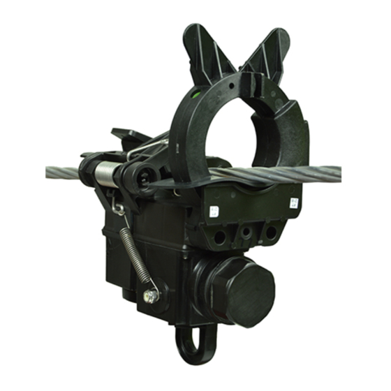
Summary of Contents for Eaton GridAdvisor Series II
- Page 1 COOPER POWER Smart Sensor SERIES Effective June 2016 MN915001EN Supersedes S1150-20-1 (October 2014) GridAdvisor ™ Series II smart sensor installation instructions Note: This document applies to product serial numbers that contain 12 characters hexadecimal formatting...
-
Page 2: Disclaimer Of Warranties And Limitation Of Liability
CONTENTS OF THIS DOCUMENT SHALL NOT BECOME PART OF OR MODIFY ANY CONTRACT BETWEEN THE PARTIES. In no event will Eaton be responsible to the purchaser or user in contract, in tort (including negligence), strict liability or otherwise for any special, indirect, incidental or consequential damage or loss whatsoever, including but not limited to... -
Page 3: Table Of Contents
Contents DISCLAIMER OF WARRANTIES AND LIMITATION OF LIABILITY ........ii Safety for life . -
Page 4: Safety For Life
FOR LIFE FOR LIFE Eaton meets or exceeds all applicable industry standards relating to product safety in its Cooper Power™ series products. We actively promote safe practices in the use and maintenance of our products through our service literature, instructional training programs, and the continuous efforts of all Eaton employees involved in product design, manufacture, marketing, and service. -
Page 5: Introduction
Std 495™-2007 standard “Guide for Testing Faulted a cellular provider using CDMA technology. Circuit Indicators” making them suitable for underground applications. The GridAdvisor Series II smart sensor saves Inside the battery compartment is a small slot for inserting both operation and maintenance dollars by reducing drive the SIM card on the inside wall (Figure 1). -
Page 6: Forcing Over The Air Service Provision (Otasp) (Verizon ® Only)
GridAdvisor Series II smart sensor Forcing over the air service provision (OTASP) Installing battery (Verizon only) ® Remove sensor barrel cap to access battery compartment. Take care not to lose the gasket located If the cellular provider being utilized with GridAdvisor Series on inside of cover. -
Page 7: Underground Distribution Circuits
Proper primary cable preparation is necessary for the Attach one or two strands of the concentric neutral GridAdvisor Series II smart sensor acting as a faulted wrapped around the cable to the tie-off tab on the elbow. circuit indicator to work reliably on underground distribution Terminate all of the remaining neutral wires just below circuits. -
Page 8: Installation Of Smart Sensor - Underground Application
GridAdvisor Series II smart sensor 15.2/26.3 kV 200 A LE225 LOADBREAK 15.2/26.3 kV 15.2/26.3 kV 200 A 200 A LE225 LE225 LOADBREAK LOADBREAK Figure 4. Figures A and B show proper installation of smart sensor on prepared conductor. Figure C shows incorrect placement for installation. -
Page 9: Installation Of Smart Sensor - Overhead Application
Source LED Sensor display operation The GridAdvisor Series II smart sensor has two multicolor light emitting diodes (LEDs) used for annunciating functional Figure 7. Smart Sensor LED designations. tasks and the status of the smart sensor. Each LED will be referred to as Source and Load LED in the context of the labels found on sensor per Figure 7 . -
Page 10: Led Installation Indication
GridAdvisor Series II smart sensor LED installation indication The LEDs provided on the GridAdvisor Series II smart sensor provide annunciation during the installation of device to verify proper load current is present. Table 2. GridAdvisor Series II Smart Sensor LEDs Provided... -
Page 11: Appendix A: Regulatory Information
GridAdvisor Series II smart sensor Appendix A: Regulatory information Radio frequency (RF) exposure In accordance with FCC requirements of human exposure to radio frequency fields, the radiating element shall be installed such that a minimum separation distance of 20 cm Compliance information is maintained. - Page 12 2300 Badger Drive Waukesha, WI 53188 Eaton.com/cooperpowerseries © 2016 Eaton All Rights Reserved Printed in USA Eaton is a registered trademark. For Eaton’s Cooper Power series Publication No. MN915001EN product information June 2016 All trademarks are property call 1-877-277-4636 or visit: E0013X41G10 REV01 of their respective owners.


Need help?
Do you have a question about the GridAdvisor Series II and is the answer not in the manual?
Questions and answers