Table of Contents
Advertisement
Available languages
Available languages
DTW14FL
DTW14FL
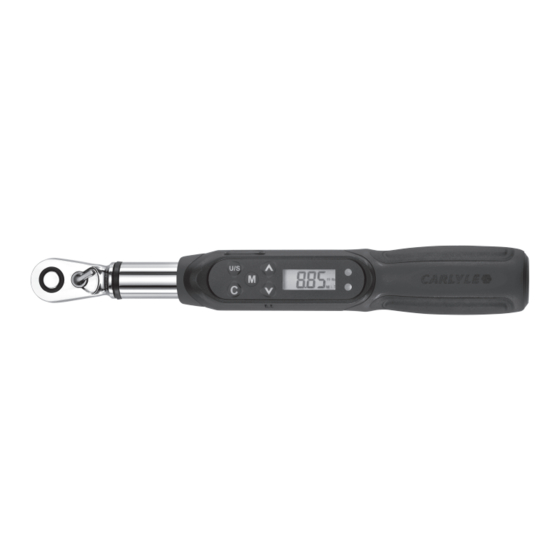
1/4" Dr. Digital Torque Wrench
1/4" Torque Range . . . . . . . . . . . . . . . . . . . . . . . . . . . . . 0.44 ft.-lbs.-8.85 ft.-lbs.
Accuracy (*1) . . . . . . . . . . . . . . . . . . . . . . . . . . . . . . . . . .(CCW ±3%) (CW ±4%)
Data Memory Values . . . . . . . . . . . . . . . . . . . . . . . . . . . . . . . . . . . . . . . . . . . 50
Number of Presets . . . . . . . . . . . . . . . . . . . . . . . . . . . . . . . . . . . . . . . . . . . . . . . 9
Operation Modes . . . . . . . . . . . . . . . . . . . . . . . . . . . . . . . . . . . . Peak Hold/Track
Unit Selection . . . . . . . . . . . . . . . . . . . . . . . . . . . . . . . . ft-lb, in-lb, N-m, & kg-cm
Head Type . . . . . . . . . . . . . . . . . . . . . . . . . . . . . . . . . . . . . . . . . . . . . Fixed Head
Gear teeth . . . . . . . . . . . . . . . . . . . . . . . . . . . . . . . . . . . . . . . . . . . . . . . . . . . . 60
Audible Alarm . . . . . . . . . . . . . . . . . . . . . . . . . . . . . . . . . . . . . . . . . . . . . . . . . Yes
Buttons . . . . . . . . . . . . . . . . . . . . . . . . . . . . . . . . . . . . . . . . . . . . . . . . . . . . . . . . 5
LED Indicator . . . . . . . . . . . . . . . . . . . . . . . . . . . . . . . . . . . . . . . . . . . . . . 2 LED's
Batteries . . . . . . . . . . . . . . . . . . . . . . . . . . . . . . . . . . . . . . . . . . . . . . . . . . . 1 AAA
Battery Life-Continuous Operation (*2) . . . . . . . . . . . . . . . . . . . . . . . . . . . 12 Hrs
Battery Life-Standby (*2) . . . . . . . . . . . . . . . . . . . . . . . . . . . . . . . . . . . . . . 1 Year
Operating Temperature . . . . . . . . . . . . . . . . . . . . . . . . . . . . . . . . . .14ºF ~ 140ºF
Storage Temperature . . . . . . . . . . . . . . . . . . . . . . . . . . . . . . . . . . . . -4ºF ~ 158ºF
Humidity . . . . . . . . . . . . . . . . . . . . . . . . . . . . . . . . . .Up to 90% non-condensing
DTW14FL
SPECIFICATIONS
1
WARNING
AlwAys reAd
instructions
before using
tools
AlwAys weAr
sAfety
goggles
not
wAterproof
Rev. 12/11/14
Advertisement
Table of Contents

Related Manuals for Napa Carlyle DTW14FL


Summary of Contents for Napa Carlyle DTW14FL
- Page 1 DTW14FL DTW14FL 1/4" Dr. Digital Torque Wrench SPECIFICATIONS WARNING 1/4" Torque Range ......0.44 ft.-lbs.-8.85 ft.-lbs. Accuracy (*1) .
-
Page 2: Specifications
SPECIFICATIONS Notes from Page 1: accuracy of the torque wrench, calibration should be performed once a year or every 5,000 cycles, whichever The accuracy of the readout is guaranteed from 20% to 100% comes first. Accuracy is based on the zero degree of offset of maximum range + /- 1 increment. -
Page 3: Features And Functions
FEATURES AND FUNCTIONS 15 16 Head Repair Kit 18 17 1. Reversible Ratchet Head 6. Anti-slip Handle 11. Power On/Clear Button 15. Torque Value Readout 2. Direction Lever 7. Battery Cover 12. Pre-Set Number Select 16. Unit Of Measure 3. Communication Port 8. Ratchet Drive Button 17. - Page 4 REPLACING THE HEAD KIT (CONT.) DISASSEMBLY Step 1: Take off the cover and spring by tip-end handle. See Fig. 1 Fig. 1 Fig. 2 Step 2: Use the tweezers to take out the square drive, pawl, and spring cap by the sequence. See Fig. 2 DTW14FL Rev. 12/11/14...
- Page 5 REPLACING THE HEAD KIT (CONT.) Step 3: Pick out the stator using side-cutter. Then the switch, spring, and steel ball can be removed simultaneously by tweezers. See Fig. 3 Fig. 3 Fig. 4 RE-ASSEMBLY Step 1: Use tweezers to put spring and steel ball on the switch carefully. See Fig. 4 DTW14FL Rev. 12/11/14...
- Page 6 REPLACING THE HEAD KIT (CONT.) RE-ASSEMBLY (cont.) Step 2: Press the switch by finger and put the stator in at the same time. Use flat head screwdriver to press them to its position. See Fig. 5 Fig. 5 Fig. 6 Step 3: Put in spring, spring cap, and pawl. Hold it by hand to prevent the pawl falling down. Then put in the square drive to engage the teeth. See Fig. 6 DTW14FL Rev. 12/11/14...
-
Page 7: Battery Installation
REPLACING THE HEAD KIT (CONT.) RE-ASSEMBLY (cont.) Step 4: Assemble the cover and the spring in advance. Use tip-end handle to put the spring in groove and press it. Assembling finished. See Fig. 7 Fig. 7 BEFORE USING THE WRENCH BATTERY INSTALLATION • Remove the battery cap. -
Page 8: Power-On Reset
POWER ON/RESET NOTE: • Press to power on the digital torque wrench. If an external force is being applied to the torque wrench during power-on/reset or wake up period, an • Pressing can also be used to reset the torque initial torque will be shown in the display. Some or all wrench before use. the lights will illuminate and the wrench will sound a continuous alarm tone. To clear the display and stop the alarm press the button. LOW BATTERY VOLTAGE PROTECTION • If the battery voltage is below 2.3 volts, the wrench will highlight the battery symbol and after a few moments turn off. - Page 9 RESETTING PRESET VALUES Torque Wrench comes with 9 Preset values pre-installed at the factory. To change a preset value stored in memory: Pre-Set Memory Indicator: M1 1. Press the memory button repeatedly to Press for immediate use. access the preset value to be changed. (e.g. M5) 2.
-
Page 10: Track Mode
TRACK MODE Track Mode: This mode allows the operator to visually monitor the amount of load that is being applied. Visual and auditory aids assist the operator in maintaining a consistent torque. After setting the (T) Track mode and assigning a Memory Pre-Set to use, operator can begin to apply load to the wrench. As a load is gradually applied to the wrench, the display will show the operator the amount of torque on the fastener. Flashing green light and intermittent tone at 90% of desired torque When 90% of the desired torque is reached, the green lights will begin to flash and and alarm tone will beep... - Page 11 PEAK HOLD MODE ( conT Viewing Peak Hold Values: 1. Press and hold the button for 2-3 seconds. "nodE" appears in the display. 2. Press the button again and the display will alternate between the last stored value and the location to which it was assigned. 3. To display a different torque value stored in the Peak Hold memory, use the buttons to navigate to the desired location.
- Page 12 NOTES Memory Prest Newton meters inch/pounds foot/pounds kilogram/centimeters angle Location # (N-m) (in - lb) (ft - lb) (kg -cm) (degree º) DTW14FL Rev. 12/11/14...
- Page 13 DTW14FL DTW14FL Torquímetros digitale 1/4" ESPECIFICACIONES ADVERTENCIA Rango de torsión 1/4" ......0.44-8.85 libras-pie sieMpre Precisión (*1).
- Page 14 ESPECIFICACIONES Notas de las página 1: se debe realizar una calibración una vez al año o cada 5,000 ciclos, cualquiera que viene siendo primero. La precisión de la lectura de salida está garantizada del 20% al 100% del máximo rango de incremento + /- 1. La precisión La precisión se basa en el grado cero de desplazamiento del de torsión es un valor típico.
- Page 15 CARACTERÍSTICAS Y FUNCIONES 15 16 Equipo de reparación de cabeza 18 17 1. Cabeza de trinquete reversible 5. Lámparas indicadoras DEL 11. Botón de encendido/borrar de torsión 2. Manivela de sentido 6. Mango anti-deslizante 12. Botón de selección de 16. Unidad de mediición 3.
- Page 16 REPOSICIÓN DEL JUEGO DE CABEzA DESENSAMBLE Paso 1: Quite la tapa y resorte por el mango de extremo de punta. Ver la fig. 1 Fig. 1 Fig. 2 Paso 2: Use las pinzas para extraer el encaje cuadrado, trinquete tapa de resorte según la secuencia. Ver la fig. 2 DTW14FL Rev.
- Page 17 REPOSICIÓN DEL JUEGO DE CABEzA Paso 3: Extraiga el estator usando el cortador lateral. Luego se pueden extraer simultáneamente el interruptor, resorte y bola de acero con las pinzas. Ver la fig. 3 Fig. 3 Fig. 4 REENSAMBLE Paso 1: Use las pinzas para colocar cuidadosamente el resorte y bola de acero en el interruptor.
- Page 18 REPOSICIÓN DEL JUEGO DE CABEzA REENSAMBLE (continuación) Paso 2: Presione el interruptor con el dedo e inserte el estator al mismo tiempo. Use el destornillador plano para presionarlos en su lugar. Ver la fig. 5 Fig. 5 Fig. 6 Paso 3: Inserte el resorte, la tapa del resorte y el trinquete. Sosténgalo con la mano para prevenir la caída del trinquete. Luego colóquelo en el encaje cuadrado para engranar los dientes.
-
Page 19: Instalación De La Batería
REPOSICIÓN DEL JUEGO DE CABEzA REENSAMBLE (continuación) Paso 4: Ensamble la tapa y el resorte anticipadamente. Use el mango del extremo de punta para colocar el resorte en la ranura y presiónalo. El ensamble está terminado. Ver la fig. 7 Fig. - Page 20 ENCENDIDO/REAJUSTE NOTA: • Oprima para encender el torquímetro digital. Si se aplica una fuerza externa al torquímetro durante el periodo de encendido/reajuste, o al sacarlo del • Al oprimirlo, se puede reajustar el torquímetro modo suspendido, se indicará una torsión inicial en antes del uso. el despliegue. Algunas de las lámparas se iluminarán y la llave sonará un tono de alarma continuo. Para borrar el despligue y parar la alarma, oprima el botón.
- Page 21 REAJUSTE DE VALORES DE PRECOLOCACIÓN El torquímetro viene con 9 valores pre-ajustados desde la fábrica. To change a preset value stored in memory: Indicador de memoria pre-ajustado: M1 Oprima para uso inmediato. 1. Oprima el botón de memoria repetidamente para acceder el valor pre-ajustado a cambiarse. (e.g. M5) 2. Oprima el botón para cambiar las unidades de medición si sea requerido.
-
Page 22: Modo De Rastreo
MODO DE RASTREO Modo de rastreo: Este modo le permite al operador visualmente monitorear la cantidad de carga que se está aplicando. Recursos visuales y auditivos le ayudarán al operador a mantener una torsión consistente. Después de ajustar el modo de rastreo (T) y asignar un pre-ajuste de memoria a usarse, el operador puede comenzar a aplicar carga al torquímetro. En la medida que se aplique una carga gradualmente al torquímetro, el despliegue le mostrará... - Page 23 MODO DE RETENCIÓN DE PICOS Examinando los valores de retención de picos: 1. Oprima y sostenga el botón durante 2 a 3 segundos. "nodE" aparece en el despliegue. 2. Oprima el botón de nuevo y el despliegue alternará entre el último valor guardado y la ubicación a la cual éste fue asignado.
- Page 24 NOTAS Preajuste de memoria Metros Newton Pulgadas/pie Libras/pie Kilogramo/centímetros ángulo Localización # (N-m) (in - lb) (ft - lb) (kg -cm) (grado º) DTW14FL Rev. 12/11/14...