Table of Contents
Advertisement
Available languages
Available languages
Quick Links
TW12TD36
TW12TD36
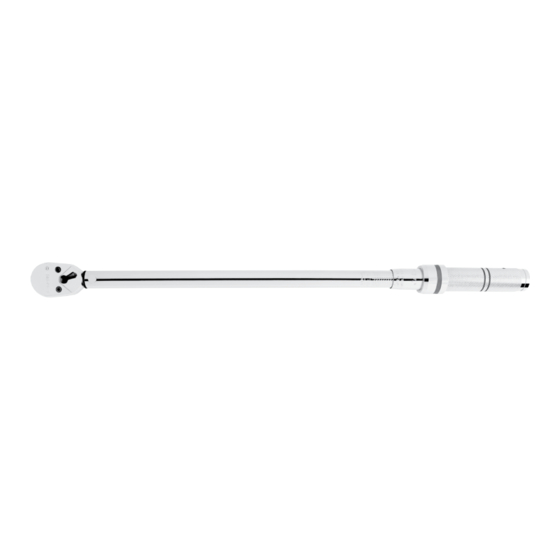
1/2" Tear Drop Fixed Head Torque Wrench
1/2" Torque Range . . . . . . . . . . . . . . . . . . . . . . . . . . . . . . . . . . . . . . 30-250 ft. lbs.
Torque Accuracy . . . . . . . . . . . . . . . . . . . . . . . . . . . . . . . . . . CW±3%, CCW±5%
Unit Selection . . . . . . . . . . . . . . . . . . . . . . . . . . . . . . . . . . . . . . . . . . . . Ft.lbs., N-m
Head Type . . . . . . . . . . . . . . . . . . . . . . . . . . . . . . . . . . . . . . . . . . . . . . . . . . . Fixed
Gear Teeth . . . . . . . . . . . . . . . . . . . . . . . . . . . . . . . . . . . . . . . . . . . . . . . . . . . . . 36
TW12TD36
SPECIFICATIONS
1
WARNING
ALWAYS READ
INSTRUCTIONS
BEFORE USING
TOOLS
ALWAYS WEAR
SAFETY
GOGGLES
NOT
WATERPROOF
Rev. 06/08/16
Advertisement
Table of Contents

Related Manuals for Napa CARLYLE TW12TD36


Summary of Contents for Napa CARLYLE TW12TD36
- Page 1 TW12TD36 TW12TD36 1/2" Tear Drop Fixed Head Torque Wrench SPECIFICATIONS WARNING 1/2" Torque Range ........30-250 ft. lbs. ALWAYS READ Torque Accuracy .
-
Page 2: Warranty
If the • The wrench should be sent in for calibration once every year manual or product labels are lost or not legible, contact NAPA or every 5,000 cycles for re-calibration. -
Page 3: Features And Functions
FEATURES AND FUNCTIONS Head Repair Kit 1. Reversible Ratchet Head 3. Major Scale 5. Ratchet Drive 2. Direction Lever 4. Minor Scale 6. Anti-slip Handle REPLACEMENT PARTS AVAILABLE AS: RSTW12TD36CS Blow Mold Case for TW12TD36 RSTW12TD36HRP Head Repair Kit for TW12TD36 No other internal parts are available due to the sensitivity of this professional model. - Page 4 REPLACING THE HEAD KIT (CONT.) Step 2: Insert the pawl spring into the handle spring hole. See fig. 2 Fig. 2 Step 3: Place the steel ball on top of the pawl spring. See fig. 3 Fig. 3 Step 4: Insert the switch with the O-ring attached into the hole on the ratchet head making sure the tail of the switch is pointing towards the handle.
- Page 5 REPLACING THE HEAD KIT (CONT.) Step 5: Insert the pawl with the square hole onto the switch and the circle hole facing you. See fig. 5 Fig. 5 Step 6: Insert the driver into the ratchet head aligning the teeth on the driver with the teeth on the pawl. See fig. 6 Fig.
-
Page 6: Operation
REPLACING THE HEAD KIT (CONT.) Step 8: Fasten the lid to the ratchet head with lid screws. See fig. 8 Test the functionality by making sure the driver turns and the switch can pivot in both directions. Fig. 8 OPERATION 1. - Page 7 MAINTANENCE 1. The internal mechanism of the torque wrench has been calibrated and lubricated before final assembly. DO NOT attempt to open the wrench's internal mechanism for any reason. Doing so will void the warranty. 2. Do not submerge the torque wrench in water or any other liquids.
-
Page 8: Especificaciones
TW12TD36 TW12TD36 Torquímetros de Cabeza Fija Tipo Pera 1/2" ESPECIFICACIONES ADVERTENCIA Rango de Torsión 1/2" ......30 N-m / 250 libras-pie SIEMPRE LEA LAS Precisión de Torsión. - Page 9 No sumerja esta unidad en ningún fluido. comuníquese con NAPA por algunos repuestos. Si el operador no • Los torquímetros debe ser recalibrados si se lleguen a caer domina el idioma inglés, las instrucciones del producto y de seguridad...
-
Page 10: Características Y Funciones
CARACTERÍSTICAS Y FUNCIONES Equipo de reparación de cabeza 1. Cabeza de trinquete reversible 3. Escala mayor 5. Encaje de trinquete 2. Manivela de sentido 4. Escala menor 6. Mango anti-deslizante LAS PARTES DE REPUESTO DISPONIBLES COMO: RSTW12TD36CS Estuche moldead por soplado para TW12TD36 RSTW12TD36HRP Equipo de reparación de cabeza paraW12TD36 Ninguna otra parte está... - Page 11 REPOSICIÓN DEL EQUIPO DE CABEZA Step 2: Inserte el resorte del trinquete en el agujero del resorte del mango. Ver la fig. 2 Fig. 2 Paso 3: Coloque la bola de acero en la parte superior del resorte del trinquete. Ver la fig. 3 Fig.
- Page 12 REPOSICIÓN DEL EQUIPO DE CABEZA Paso 5: Inserte el trinquete con el agujero cuadrado en el interruptor y el agujero circular orientado hacia usted. Ver la fig. 5 Fig. 5 Paso 6: Inserte el conductor en la cabeza del trinquete, alineando los dientes en el conductor con los dientes del trinquete.
-
Page 13: Operación
REPOSICIÓN DEL EQUIPO DE CABEZA Paso 8: Sujete la tapa a la cabeza de la carraca con los tornillos de la tapa. Ver la fig. 8 Compruebe la funcionalidad al asegurar que el conductor gire y que el interruptor pivote en ambos sentidos. Fig. -
Page 14: Mantenimiento
MANTENIMIENTO 1. El mecanismo interno del torquímetro ha sido calibrado y lubricado antes del ensamble final. NO intente abrir el mecanismo interno del torquímetro por ningún motivo. Si esto se llegara a pasar, se anularía la garantía. 2. No sumerja el torquímetro en agua ni en ningún otro líquido.
Need help?
Do you have a question about the CARLYLE TW12TD36 and is the answer not in the manual?
Questions and answers