Table of Contents
Advertisement
Available languages
Available languages
Quick Links
TW12RHQR
TW12RHQR
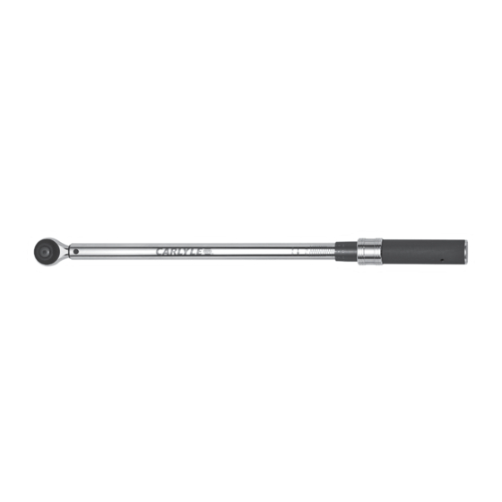
1/2" Round Head Click Style Torque Wrench
1/2" Torque Range . . . . . . . . . . . . . . . . . . . . . . . . . . . . . . . . . . . . . . 30-250 ft. lbs.
Torque Accuracy . . . . . . . . . . . . . . . . . . . . . . . . . . . . . . . . . . . CW±4% CCW±4%
Unit Selection . . . . . . . . . . . . . . . . . . . . . . . . . . . . . . . . . . . . . . . . . . . . Ft.lbs., N-m
Head Type . . . . . . . . . . . . . . . . . . . . . . . . . . . . . . . . . . . . . . . . . . . . . . . . . . . Fixed
Gear Teeth . . . . . . . . . . . . . . . . . . . . . . . . . . . . . . . . . . . . . . . . . . . . . . . . . . . . . 72
TW12RHQR
SPECIFICATIONS
1
WARNING
AlwAys reAd
instructions
before using
tools
AlwAys weAr
sAfety
goggles
not
wAterproof
Rev. 12/16/13
Advertisement
Table of Contents

Related Manuals for Napa Carlyle TW12RHQR


Summary of Contents for Napa Carlyle TW12RHQR
- Page 1 TW12RHQR TW12RHQR 1/2" Round Head Click Style Torque Wrench SPECIFICATIONS WARNING 1/2" Torque Range ........30-250 ft. lbs. AlwAys reAd Torque Accuracy .
-
Page 2: Warranty
WARNING - FOLLOW THESE RULES FOR SAFE OPERATION! FAILURE TO OBSERVE THESE WARNINGS COULD RESULT IN INJURY this instruction MAnuAl contAins iMportAnt sAfety inforMAtion. reAd this instruction MAnuAl cArefully And understAnd All inforMAtion before operAting this tool. • To safeguard torque accuracy avoid keeping tool set at high loads for long periods of time. When finished reset back to zero. • Do not operate without eye or hand protection. -
Page 3: Features And Functions
FEATURES AND FUNCTIONS Head Repair Kit 1. Reversible Ratchet Head 3. Major Scale 5. Locking Collar 7. Anti-slip Handle 2. Wrench Body 4. Minor Scale 6. Ratchet Drive REPLACEMENT PARTS AVAILABLE AS: RSTW12RHQREC End Cap for TW12RHQR RSTW12RHQRHRP Head Repair Kit for TW12RHQR RSTW12RHQRCS Blow Mold Case for TW12RHQR No other internal parts are available due to the sensitivity of this professional model. Please utilize the repair facility listed under the warranty statement for all repairs in and out of warranty. - Page 4 REPLACING THE HEAD KIT (CONT.) Fig. 2 Step 2: Apply a small amount of grease to the three points indicated by arrows. See Fig. 2 Fig. 3 Step 3: Position the Pawl, #3 and the heart spring, #4 as indicated in Fig. 3 Fig. 4 Step 4: With the pawl and heart spring in place on the drive. Place the assembly inside the head of the ratchet. Be sure the drive is inserted on the recessed side of the head.
- Page 5 REPLACING THE HEAD KIT (CONT.) Step 6: Fasten the drive nut to the drive with a 10mm socket. Tighten the nut a quarter past snug and proceed to assemble the socket head using in this order using part #6. See Fig. 6. Fig. 6 Step 7: Secure drive in a vise or with a pair of pliers. Tighten nut while holding the drive end of the wrench See Fig. 7. Fig.7 Step 8: Install part #9, 8, 7 in that order. While holding these components in place install with a #10 screw into the center of the components and tighten with a T-8 driver until fully secured. Overtightening may effect how the ratchet can switch direction. See Fig. 8. To ensure the drive is fully functioning turn the direction plate from CW to CCW taking time to spin the drive in each direction.
-
Page 6: Operation
OPERATION 1. To unlock the handle, hold the body firmly and pull and Minor Scale hold down the locking collar (A). This will allow you to rotate the handle clockwise or counter clockwise to your desired torque measurement. 2. Set the desired torque by rotating the wrench body clockwise or counter clockwise. For example 45 ft. lbs: a. Rotate the handle until the zero graduation on Major Scale (B) Locking Collar (A) Handle minor scale is lined up with the vertical line and is even with 40 ft. lbs. on the major scale. b. Then slowly rotate the handle clockwise and set the Apply Force minor scale to five (5). 3. Release the locking collar to lock the handle in place. 4. Install the proper socket or attachment to the square drive end and apply to the object receiving torque. Rotate the wrench in a clockwise or counter clockwise steady motion until you feel/hear a "CLICK" sound. 5. IMPORTANT: ALWAYS reset the major scale torque measurement back to "ZERO" when you are finished using the wrench. This will ensure the internal body spring maintains accurate tension which prolongs the life and accuracy of the product. MAINTANENCE 1. The internal mechanism of the torque wrench has been calibrated and lubricated before final assembly. DO... -
Page 7: Especificaciones
TW12RHQR TW12RHQR Torquímetros Tipo "Clicker" de Cabeza Redonda 1/2" ESPECIFICACIONES ADVERTENCIA Rango de Torsión 1/2" ......30 N-m / 250 libras-pie sieMpre leA lAs Precisión de Torsión. - Page 8 ADVERTENCIA - ¡SIGA LAS REGLAS PARA UNA OPERACIÓN SEGURA! HACER CASO OMISO A ESTAS ADVERTENCIAS PODRÍA OCASIONAR LESIONES ESTE Manual InSTRuCTIVO COnTIEnE InFORMaCÓn IMPORTanTE DE SEGuRIDaD. lEa ESTE Manual InSTRuCTIVO CuIDaDOSaMEnTE Y COMPREnDa TODa la InFORMaCIÓn anTES DE OPERaR ESTa HERRaMIEnTa.
-
Page 9: Características Y Funciones
CARACTERíSTICAS Y FUNCIONES Equipo de reparaciónde cabeza 1. Cabeza de trinquete reversible 3. Escala mayor 5. Cuello que bloquea 7. Mango anti-deslizante 2. Cuerpo 4. Escala menor 6. Encaje de trinquete LAS PARTES DE REPUESTO DISPONIBLES COMO: RSTW12RHQREC Tapa terminal para TW12RHQR RSTW12RHQRHRP Equipo de reparación de cabeza RSTW12RHQRCS Estuche moldead por soplado para TW12RHQR para TW12RHQR Ninguna otra parte está disponible debido a la sensibilidad de este modelo profesional. - Page 10 REPOSICIÓN DEL EQUIPO DE CABEZA Fig. 2 Paso 2: Aplique una pequeña cantidad de grasa en los tres puntos indicados por las flechas. Ver la fig. 2 Fig. 3 Paso 3: Posicione el trinquete, #3 y el resorte en forma de corazón, #4 según se indique en la fig. 3 Fig. 4 Paso 4: Con el trinquete y el resorte en forma de corazón en su lugar en el impulsor, coloque el ensamble adentro de la culata de la carraca.
- Page 11 REPOSICIÓN DEL EQUIPO DE CABEZA Paso 6: Sujete la tuerca del impulsor en el impulsor con un casquillo 10mm. Apriete la tuerca un cuarto de vuelta más allá de su posición de apretado y siga con el ensamble de la cabeza del casquillo usando, en este orden, la parte #6. Ver la fig. 6. Fig. 6 Paso 7: Sujete el impulsor en un banco de tornillo o con unas alicates. Apriete la tuerca, sosteniendo el extremo de del impulsor con la llave. Ver la fig. 7. Fig.7 Paso 8: Instale las partes #9, 8, 7 en dicho orden. Al mismo tiempo que se sostenga estos componentes en su lugar, instale con un tornillo #10 en el centro de los componentes y apriete con un impulsor T-8 hasta que estén plenamente sujetados. El sbore apretado puede afectar cómo el...
-
Page 12: Operación
OPERACIÓN 1. Para abrir la manija, lleve a cabo el cuerpo firmemente cuando ha terminado de usar el torquímetro. Así se y tire y mantenga el cuello que bloquea (a). Esto le asegurará que el resorte interno del cuerpo mantenga una permitirá girar el mango en el sentido de las agujas tensión precisa lo cual prolonga la vida útil y la precisión del reloj o en el contrasentido de las agujas del reloj del producto. hasta lograr su medida deseada de torsión. 2. Ajuste la torsión deseada al girar el cuerpo del Escala Menor torquímetro en el sentido o contrasentido de las agujas del reloj. Por ejemplo 45 libras-pie: a. Gire el mango hasta que la graduación a cero en la escala menor esté alineada con la línea vertical y que esté paralela con 40 libras-pie en la escala principal.
Need help?
Do you have a question about the Carlyle TW12RHQR and is the answer not in the manual?
Questions and answers