Table of Contents
Advertisement
Quick Links
Owner's Manual
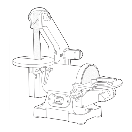
1" X 30" BELT and 5" DISC SANDER
QUESTION...
1•847•780•6120
Visit us on the web at www.southerntechllc.com
You will need this manual for safety instructions, operating procedures, and warranty.
Put it and the original sales invoice in a safe, dry place for future reference.
Model No. BD1502
17-0303
Advertisement
Table of Contents

Subscribe to Our Youtube Channel
Related Manuals for PowerTec BD1502


Summary of Contents for PowerTec BD1502
- Page 1 Model No. BD1502 Owner’s Manual 1" X 30" BELT and 5" DISC SANDER QUESTION... 1•847•780•6120 Visit us on the web at www.southerntechllc.com You will need this manual for safety instructions, operating procedures, and warranty. Put it and the original sales invoice in a safe, dry place for future reference.
-
Page 2: Table Of Contents
TABLE OF CONTENTS PRODUCT SPECIFICATIONS SECTION PAGE Horsepower ....... . . 1/3 Voltage . -
Page 3: Safety Rules
GENERAL SAFETY RULES • Keep children and visitors away. Your shop is a potentially WARNING dangerous environment. Children and visitors can be For your own safety, read and understand all warnings and injured. operating instructions before using any tool or equipment. •... -
Page 4: Assembly
ASSEMBLY UNPACKING ASSEMBLE THE DUST CHUTE Refer to Figure 1. Refer to Figure 2 Check for shipping damage. Check immediately whether • Slide the groove in the dust chute onto the sanding disc all parts and accessories are included. guard casting as shown. Secure the dust chute to the The sander comes assembled as one unit. -
Page 5: Assemble The Sanding Belt Table
To adjust sanding disc table Figure 6 • Place a square on the table with the ruler side against the sanding disc. The table should be 90° to the sanding disc. • If the table is not 90° to the sanding disc, loosen the locking knobs and tilt table up and down until it is 90°... -
Page 6: Replacing The Sanding Belt
To level • Hold and apply moderate pressure to the belt tracking knob assembly to release the belt tension enough to • A leveling screw is provided to aid in leveling the belt remove the old belt. NOTE: The belt tracking knob is disc table. -
Page 7: Backstop
• Replace the upper and side belt guards and secure in • Peel the old sanding disc from the sanding wheel. Clean place with the belt guard locking knob. the sanding wheel with mineral spirits. Make sure the surface is clean and dry. •... -
Page 8: Mounting The Sander To Work Surface
MOUNTING THE SANDER TO WORK GROUNDING INSTRUCTIONS SURFACE WARNING Refer to Figure 14 Improper connection of equipment grounding conductor CAUTION can result in the risk of electrical shock. • The machine should be grounded while in use to protect Properly mount the sander to a workbench or stand if operator from electrical shock. -
Page 9: Motor
Figure 16 • There is a green grounding wire fastened to the frame of the machine to provide Shock Protection. Do not Grounded outlet Box disconnect the Grounding Wire from the frame. Grounding • The Motor is rated for use at 120 Volts. Adapter Means •... -
Page 10: Operation
OPERATION ON/OFF SWITCH Figure 19 Refer to Figure 18 • To turn sander ON place the ON/OFF switch in the ON position. • To turn the sander OFF, place the ON/OFF switch in the OFF position. Figure 18 ON/OFF Slot On Work Table Switch SURFACE SANDING ON SANDING BELT Hold the workpiece firmly with both hands. -
Page 11: Maintenance
MAINTENANCE WARNING WARNING For your own safety, turn the switch OFF and remove Any attempt to repair or replace electrical parts on this tool the plug from the electrical outlet before adjusting or may be hazardous. Repairs should be done by a qualified performing maintenance or lubrication work on the service technician. -
Page 12: Parts Illustration
1"X 5" BELT/DISC SANDER PARTS ILLUSTRATION... - Page 13 1"x 5" BELT/DISC SANDER PARTS LIST Key# Part# Description Specifications Qty Key# Part# Description Specifications Qty BD1510001 Philips Screw Assy. M6x18 BD1510038 Hex Bolt M10x25 BD1510002 Rubber Feet BD1510039 Belt Support BD1510003 Philips Screw Assy. M4x12 BD1510040 Inner Hex Set Screw M6x20 BD1510004 Bottom Cover...
-
Page 14: Troubleshooting
TROUBLESHOOTING SYMPTOM POSSIBLE CAUSE(S) CORRECTIVE ACTION Sanding Grains 1. Sanding belt/disc has been stored 1. Ensure sanding accessories are stored away from easily rub off belt in an incorrect environment. extremely hot or dry temperatures. or discs. 2. Sanding belt/disc has been 2. -
Page 15: Warranty
30- DAY SATISFACTION GUARANTEE POLICY During the first 30 days after the date of purchase, if you are dissatisfied with the performance of this POWERTEC tool for any reason, you may return the tool to the retailer from which it was purchased for a full refund or exchange. You must present proof of purchase and return all original equipment packaged with the original product. - Page 16 Southern Technologies, LLC 3816 Hawthorn CT, Waukegan, IL 60087...
Need help?
Do you have a question about the BD1502 and is the answer not in the manual?
Questions and answers