Table of Contents
Advertisement
Quick Links
Advertisement
Table of Contents
Troubleshooting

Related Manuals for PowerTec BD4600


Summary of Contents for PowerTec BD4600
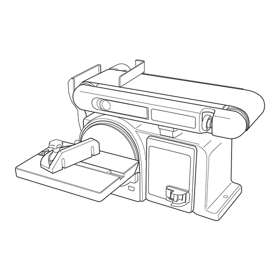
- Page 1 Model No. BD4600 Owner’s Manual 4" x 6" Belt/Disc SANDER Visit us on the web at www.southerntechllc.com You will need this manual for safety instructions, operating procedures, and warranty. Put it and the original sales invoice in a safe, dry place for future reference.
-
Page 2: Table Of Contents
TABLE OF CONTENTS PRODUCT SPECIFICATIONS SECTION PAGE Horsepower ....... . . 1/2 Voltage . -
Page 3: Safety Rules
SAFETY RULES TOOL MAINTENANCE WARNING • Turn the machine "OFF", and disconnect the machine For your own safety, read and understand all warnings from the power source prior to inspection. and operating instructions before using any tool or • Maintain all tools and machines in peak condition. Keep equipment. -
Page 4: Assembly
ASSEMBLY UNPACKING TOOLS NEEDED The following tools (not included) are needed to assemble Refer to Figure 1. and adjust the belt/disc sander: Check for shipping damage. Check immediately whether • 10 mm wrench all parts and accessories are included. • 6 mm hex wrench (supplied) •... -
Page 5: Sanding Belt Tracking Adjustment
Figure 3 To adjust: a. Turn the tracking knob clockwise to move the Work Support sanding belt away from the disc. b. Turn the tracking knob counterclockwise to move Sanding Belt Support the sanding belt toward from the disc. • Turn the switch ON and OFF again to check the adjustment;... -
Page 6: Maintenance
SQUARE THE TABLE • Remove the used sanding disc from the sanding disc plate and dispose of properly Refer to Figure 7 • Wipe the sanding disc plate clean. • Peel the backing from the new sanding disc. Align the To ensure accurate end sanding, the work table must be new sanding disc with sanding disc plate and press square to the sanding surfaces prior to using the work... -
Page 7: Horsepower
POWER SOURCE • Inspect tool cords periodically, and if damaged, have repaired by an authorized service facility. WARNING • The conductor with insulation having an outer surface Do not connect to the power source until the machine is that is green with or without yellow stripes is the completely assembled. -
Page 8: Electrical Connections
Apply enough pressure to remove material; Your Powertec 6 x 9 belt disc sander is designed and excessive pressure will reduce sanding efficiency. engineered to sand wood or wood products. Sanding of... -
Page 9: F Work Table
Figure 16 To change positions: • Use 6 mm hex key supplied to loosen (counterclock- Idler Pulley wise) the bed locking screw. Workpiece • Raise or lower the sanding bed to the desired position and tighten the bed socket screw (clockwise). OPERATIONAL NOTE: Sand long workpieces with the sanding belt in the vertical position by moving the work evenly across the sanding belt. -
Page 10: Warning
MITER GAUGE - DISC SANDER Figure 20 Refer to Figure 20 Lock Knob Mitre Gauge A miter-gauge is supplied with your sander, and can be used on the work table. • Place the miter gauge slide pole into the slot on the work table. -
Page 11: Troubleshooting
TROUBLESHOOTING SYMPTOM POSSIBLE CAUSE(S) CORRECTIVE ACTION Sanding Grains 1. Sanding belt/disc has been stored in 1. Ensure sanding accessories are stored away easily rub off belt an incorrect environment. from extremely hot or dry temperatures. or discs. 2. Sanding belt/disc has been 2. -
Page 12: Parts Illustration
4"X 6" BELT/DISC SANDER PARTS ILLUSTRATION... - Page 13 4"x 6" BELT/DISC SANDER PARTS LIST Key No. Part No. Description Specification Key No. Part No. Description Specification 1 BD4600001 Philips Screw M4x6 48 BD4600048 Screw Sleeve 2 BD4600002 Flat Washer 49 BD4600049 Connection Plate 50 BD4600050 Spring 3 BD4600003 Base Plate 51 BD4600051 Sanding Belt Tension Knob 4 BD4600004 Philips Screw ST4.2X10...
-
Page 14: Warranty
30- DAY SATISFACTION GUARANTEE POLICY During the first 30 days after the date of purchase, if you are dissatisfied with the performance of this POWERTEC tool for any reason, you may return the tool to the retailer from which it was purchased for a full refund or exchange. You must present proof of purchase and return all original equipment packaged with the original product. - Page 15 DISCLAIMER To the extent permitted by applicable law, all implied warranties, including warranties of MERCHANTABILITY or FITNESS FOR A PARTICULAR PURPOSE, are disclaimed. Any implied warranties, that cannot be disclaimed under state law are limited to one year from the date of purchase. Southern Technologies LLC. is not responsible for direct, indirect, incidental or consequential damages.
- Page 16 Southern Technologies, LLC 206 Terrace Drive Mundelein, Illinois 60060...
Need help?
Do you have a question about the BD4600 and is the answer not in the manual?
Questions and answers