H3C MSR810 Installation Manual
Hide thumbs
Also See for MSR810:
- Command reference manual (389 pages) ,
- Installation manual (65 pages) ,
- Safety manual (64 pages)
Table of Contents
Advertisement
Quick Links
Download this manual
See also:
Installation Manual
Advertisement
Table of Contents

Related Manuals for H3C MSR810


Summary of Contents for H3C MSR810
-
Page 1: Installation Guide
H3C MSR810 Routers Installation Guide Hangzhou H3C Technologies Co., Ltd. http://www.h3c.com Document version: 5W100-20150701... - Page 2 Copyright © 2015, Hangzhou H3C Technologies Co., Ltd. and its licensors All rights reserved No part of this manual may be reproduced or transmitted in any form or by any means without prior written consent of Hangzhou H3C Technologies Co., Ltd.
- Page 3 Preface The H3C MSR810 Routers Installation Guide includes three chapters, which describe the preparing for installation, installing the router, troubleshooting, chassis views and technical specifications, and LEDs. This preface includes the following topics about the documentation: Audience. • • Conventions.
- Page 4 GUI conventions Convention Description Window names, button names, field names, and menu items are in Boldface. For Boldface example, the New User window appears; click OK. > Multi-level menus are separated by angle brackets. For example, File > Create > Folder. Symbols Convention Description...
-
Page 5: Obtaining Documentation
About the H3C MSR810 Routers documentation set The H3C MSR810 Routers documentation set includes the following categories of documents: Category Documents Purposes Product description and marketing brochures Describe product specifications and benefits. specifications Hardware specifications Provides a complete guide to hardware installation... -
Page 6: Table Of Contents
Contents Preparing for installation ············································································································································· 1 Safety recommendations ·················································································································································· 1 Safety symbols ·························································································································································· 1 General safety recommendations ··························································································································· 1 Electricity safety ························································································································································ 1 ESD prevention ························································································································································· 1 Examining the installation site ········································································································································· 2 Temperature and humidity ······································································································································· 2 Cleanliness ································································································································································ 2 Cooling ······································································································································································... - Page 7 Scenario 2 ······························································································································································ 26 Scenario 3 ······························································································································································ 26 Reset button usage guidelines ······························································································································ 27 Appendix A Chassis views and technical specifications ························································································ 28 Chassis views ································································································································································· 28 MSR810 ································································································································································· 28 MSR810-W ···························································································································································· 29 MSR810-W-DB ······················································································································································ 30 MSR810-LM ··························································································································································· 31 MSR810-W-LM ······················································································································································ 32 Technical specifications ·················································································································································...
-
Page 8: Preparing For Installation
Preparing for installation Safety recommendations To avoid any equipment damage or bodily injury, read the following safety recommendations before installation. Note that the recommendations do not cover every possible hazardous condition. Safety symbols When reading this document, note the following symbols: WARNING means an alert that calls attention to important information that if not understood or followed can result in personal injury. -
Page 9: Examining The Installation Site
Keep the equipment room clean to reduce the negative effects of dusts and particles. • • Maintain the humidity and temperature levels in the acceptable range. Always wear an ESD wrist strap. Make sure the wrist strap makes good skin contact and is •... -
Page 10: Cooling
The equipment room must also meet strict limits on salts, acids, and sulfides to eliminate corrosion and premature aging of components, as shown in Table Table 3 Harmful gas limits in an equipment room Maximum concentration (mg/m 0.006 0.05 0.01 Cooling Maintain a minimum clearance of 10 cm (3.94 in) around the air vents. -
Page 11: Installation Accessories And Tools
Installation accessories and tools Figure 1 Installation accessories Cage nut 4G antenna GPS antenna WLAN antenna Ring terminal (user supplied) M6 screw M4 screw Mounting brackets Wall anchor kit Rubber feet (user supplied) (user supplied) (user supplied) Figure 2 User-supplied tools and equipment Pre-installation checklist Item Requirements... - Page 12 Item Requirements • A single-phase three-wire power receptacle with protection earth (PE) is available for filtering interference from the power grid. • The router is far away from radio transmitting stations, radar EMI prevention stations, and high-frequency devices. • Electromagnetic shielding, for example, shielded interface cables, is used as required.
-
Page 13: Installing The Router
Keep the tamper-proof seal on a mounting screw on the chassis cover intact, and if you want to open • the chassis, contact H3C for permission. Otherwise, H3C shall not be liable for any consequence. Installation prerequisites You have read "Preparing for... -
Page 14: Installing The Router
Figure 3 Installation flowchart Installing the router Mounting the router on a workbench IMPORTANT: Make sure the workbench is clean, stable, and reliably grounded. • • Maintain a minimum clearance of 10 cm (3.9 in) around the router for heat dissipation. Do not place heavy objects on the router. -
Page 15: Mounting The Router On A Wall
Figure 4 Mounting the router on a workbench Mounting the router on a wall Mark two screw hole locations on the wall. Make sure the two holes are 160 mm (6.30 in) horizontally apart. Drill holes with a minimum depth of 22 mm (0.87 in) in the marked locations. Use a hammer to tap an anchor into each hole until the anchor end is flush with the wall. -
Page 16: Installing The Router In A Rack
Figure 5 Wall-mounting the router Installing the router in a rack CAUTION: The mounting brackets can support only the weight of the router. Do not place objects on the router. To install the router in a rack: Use a mounting bracket to mark the cage nut installation holes in the front rack posts, as shown Figure Make sure the cage nut installation holes on the front rack posts are on a horizontal line. - Page 17 Figure 6 Marking cage nut installation holes Install the cage nuts, as shown in Figure Insert one ear of a cage nut into the marked installation hole. Use a flathead screwdriver to push another ear into the same hole. Figure 7 Installing cage nuts...
- Page 18 Attach mounting brackets to both sides of the router, as shown in Figure Figure 8 Attaching mounting brackets to the router Use M6 screws to attach the mounting brackets on the router to the front rack posts, as shown Figure Figure 9 Securing the router to the rack...
-
Page 19: Grounding The Router
Grounding the router CAUTION: Correctly connecting the grounding cable is crucial to lightning protection and EMI protection. When • you install and use the router, first ground the router reliably. • Ensure a minimum resistance of 5 ohms between the router and the ground. The router provides only a ring terminal. -
Page 20: Installing A 4G Sim Card
Figure 11 Connecting the grounding cable to the router Grounding screw Grounding hole Grounding the router by burying a grounding conductor in the earth ground If the installation site does not have any grounding strips, but earth ground is available, hammer a 0.5 m (1.64 ft) or longer angle iron or steel tube into the earth ground to serve as a grounding conductor. -
Page 21: Installing A Micro Sd Card
Only the MSR810-LM and MSR810-W-LM routers support 4G SIM cards. These two routers also support TD-SCDMA and WCDMA SIM cards. To install a 4G SIM card: Remove the screw on the 4G SIM card slot cover and take off the cover. -
Page 22: Installing A 4G Antenna
Installing a WLAN antenna Only the MSR810-W, MSR810-W-LM, and MSR810-W-DB routers support WLAN antennas. You can install two WLAN antennas for the MSR810-W and MSR810-W-LM routers and install four WLAN antennas for the MSR810-W-DB router. To install a WLAN antenna: Change the angle of the antenna orientation from vertical to horizontal. -
Page 23: Installing A Gps Antenna
Figure 16 Installing WLAN antennas Installing a GPS antenna Only the MSR810-LM and MSR810-W-LM routers support a GPS antenna. To install a GPS antenna: Attach the male connector of the GPS antenna to the GPS antenna port on the router. -
Page 24: Connecting The Console Cable And Setting Terminal Parameters
Figure 18 Connecting an Ethernet cable Connecting the console cable and setting terminal parameters Connecting the console cable CAUTION: The serial ports on PCs do not support hot swapping. To connect a PC to an operating router, first connect the PC end. To disconnect a PC from an operating router, first disconnect the router end. To connect the console cable: Select a configuration terminal, which can be an ASCII terminal with an RS232 serial port or a PC. - Page 25 Figure 19 Connecting the console cable Setting configuration terminal parameters Select Start > All Programs > Accessories > Communications > HyperTerminal. The Connection Description dialog box appears. Enter the name of the new connection in the Name field and click OK. Figure 20 Connection description Select the serial port to be used from the Connect using list, and click OK.
- Page 26 Figure 21 Setting the serial port used by the HyperTerminal connection Set Bits per second to 9600, Data bits to 8, Parity to None, Stop bits to 1, and Flow control to None, and click OK. NOTE: To restore the default settings, click Restore Defaults. Figure 22 Setting the serial port parameters...
- Page 27 Select File > Properties in the HyperTerminal window. Figure 23 HyperTerminal window On the Settings tab, set the emulation to VT100 or Auto Detect, and click OK. Figure 24 Setting the terminal emulation parameters...
-
Page 28: Connecting The Power Adapter
Connecting the power adapter The power adapter provided with the router has the following specifications: • AC input range—100 VAC to 240 VAC @ 50 Hz to 60 Hz. DC output voltage—12 VDC. • Only a single-phase three-wire AC receptacle is applicable to the power adapter. To connect the power adapter: Make sure the AC receptacle and the router are reliably grounded Connect the power adapter to the AC receptacle. -
Page 29: Accessing The Router For The First Time
Press Ctrl+D to access BASIC-BOOTWARE MENU Booting Normal Extend BootWare Do you want to check SDRAM? [Y/N] **************************************************************************** H3C MSR810 BootWare, Version 1.03 **************************************************************************** Copyright (c) 2004-2015 Hangzhou H3C Technologies Co., Ltd. Compiled Date : Mar 20 2015 CPU ID : 0xa CPU L1 Cache... -
Page 30: Power-On Check
Configuring basic settings for the router After the router is powered on for the first time, configure basic settings for the router. For more information, see H3C MSR Router Series Configuration Guide (V7) and H3C MSR Router Series Command Reference (V7). -
Page 31: Troubleshooting
Keep the tamper-proof seal on a mounting screw on the chassis cover intact, and if you want to open • the chassis, contact H3C for permission. Otherwise, H3C shall not be liable for any consequence. Power module failure Symptom The router cannot be powered on and the LEDs on the front panel are off. -
Page 32: Garbled Display On The Configuration Terminal
Stop bits—1. Flow control—none. Emulation—VT100. Verify that the console cable is in good condition. If the problem persists, contact H3C Support. Garbled display on the configuration terminal Symptom The configuration terminal has garbled display when the router is powered on. -
Page 33: Solution
Verify that the 4G antenna is correctly installed. Verify that the 3G/4G SIM card, card socket, and 4G antenna are in good condition. Verify that the network provided by NSP is running correctly. If the problem persists, contact H3C Support. Restoring the factory settings Scenario 1 Symptom When you replace the router, the router password is lost. -
Page 34: Reset Button Usage Guidelines
Solution Press the Reset button for a short time to reboot the router. Reset button usage guidelines The router provides the Reset button. You can use the button to reboot the system or restore the factory settings. Press the Reset button for a short time to reboot the router. Press the Reset button for more than 4 seconds to reboot the router and restore the factory settings. -
Page 35: Appendix A Chassis Views And Technical Specifications
Appendix A Chassis views and technical specifications Chassis views The figures in this appendix are for illustration only. MSR810 Figure 26 Front view (1) Power adapter receptacle (2) Gigabit Ethernet LAN ports (GE1 to GE4) (3) Gigabit Ethernet WAN port (GE0) -
Page 36: Msr810-W
MSR810-W Figure 28 Front view (1) Power adapter receptacle (2) Gigabit Ethernet LAN ports (GE1 to GE4) (3) Gigabit Ethernet WAN port (GE0) (4) Gigabit fiber port (SFP5) (5) Console port (6) USB port (7) Micro SD card slot (8) USB port... -
Page 37: Msr810-W-Db
MSR810-W-DB Figure 30 Front view (1) Power adapter receptacle (2) Gigabit Ethernet LAN ports (GE1 to GE4) (3) Gigabit Ethernet WAN ports (GE0) (4) Gigabit fiber port (SFP5) (5) Console port (6) USB port (7) Micro SD card slot (8) USB port... -
Page 38: Msr810-Lm
MSR810-LM Figure 32 Front view (1) Power adapter receptacle (2) Gigabit Ethernet LAN ports (GE1 to GE4) (3) Gigabit Ethernet WAN port (GE0) (4) Gigabit fiber port (SFP5) (5) Console port (6) USB port (7) Micro SD card slot (8) Reset button (RESET) -
Page 39: Msr810-W-Lm
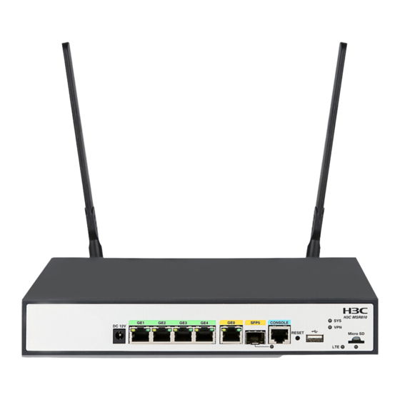
MSR810-W-LM Figure 34 Front view (1) Power adapter receptacle (2) Gigabit Ethernet LAN ports (GE1 to GE4) (3) Gigabit Ethernet WAN port (GE0) (4) Gigabit fiber port (SFP5) (5) Console port (6) USB port (7) Micro SD card slot (8) Reset button (RESET) - Page 40 Item MSR810 MSR810-W MSR810-W-DB MSR810-LM MSR810-W-LM Flash 256 MB 256 MB 256 MB 256 MB 256 MB Dimensions (H × W × D) 43.6 × 266 × 43.6 × 266 × 43.6 × 266 × 43.6 × 266 × 43.6 × 266 ×...
- Page 41 Item Specification Color Black Weight 25 g (0.88 oz ) Operating temperature –40°C to +85°C (–40°F to +185°F)
-
Page 42: Appendix B Leds
Appendix B LEDs LEDs MSR810 Figure 36 Front panel LEDs (1) GE port yellow LED (2) GE port green LED (3) System status LED (SYS) (4) Micro SD card LED (5) VPN status LED (6) SFP port LED MSR810-W Figure 37 Front panel LEDs... -
Page 43: Msr810-W-Db
MSR810-W-DB Figure 38 Front panel LEDs (1) GE port yellow LED (2) GE port green LED (3) System status LED (SYS) (4) VPN status LED (5) 2.4G WLAN LED (6) 5G WLAN LED (7) Micro SD card LED (8) SFP port LED... -
Page 44: Msr810-W-Lm
MSR810-W-LM Figure 40 Front panel LEDs (1) GE port yellow LED (2) GE port green LED (3) System status LED (SYS) (4) VPN status LED (5) 2.4G WLAN LED (6) CNDE LED (7) Micro SD card LED (8) LTE LED... - Page 45 Status Description Steady green The Micro SD card is present and has passed the test. Micro SD card LED No Micro SD card is inserted or the Micro SD card is installed incorrectly. Steady green A 4G link is present. Flashing green (8 Hz) Data is being received or transmitted on a 4G link.
-
Page 46: Index
Index A C E I L N P R S T description,37 LEDs,35 Accessing the router for the first time,22 No display on the configuration terminal,24 Chassis views,28 No response from the serial port,25 Examining the installation site,2 Power module failure,24 Pre-installation checklist,4...
Need help?
Do you have a question about the MSR810 and is the answer not in the manual?
Questions and answers