Advertisement
Advertisement
Table of Contents

Subscribe to Our Youtube Channel
Related Manuals for Vibe Slick Stereo 2


Summary of Contents for Vibe Slick Stereo 2
- Page 2 Thank you for buying VIBE, we hope you enjoy listening to your product as much as we enjoyed creating it.
-
Page 3: Limited Warranty
LIMITED WARRANTY... -
Page 4: Mounting Guidelines
MOUNTING GUIDELINES Your VIBE amplifi er is designed with a swift installation routine in mind. Please mount the amplifi er in a dry location on a solid surface. NEVER mount the amplifi er upside down as this will cause the amplifi er to over heat and will eventually damage the amplifi... -
Page 5: Ground Cable
CONNECTIONS Length of Run Current demand 0 – 4 Ft 4 – 7 Ft 7 – 10 Ft 10 – 13 Ft 13 – 16 Ft 16 – 19 Ft 19 – 22 Ft 22 – 28 Ft 0–20 amps 20–35 amps 35–50 amps 50–65 amps... - Page 6 Slick Stereo 2 TERMINALS AND CONNECTIONS 1. Low level input For connection to any source (head unit) with a low level output. This is your RCA output from the source (headunit) 2. Low level output RCA output used to connect an additional amplifi er or audio device.
- Page 7 Slick Stereo 2 STEREO WIRING CONFIGURATION 2 OHM MINIMUM BRIDGED WIRING CONFIGURATION 4 OHM MINIMUM...
- Page 8 Slick Stereo 4 TERMINALS AND CONNECTIONS 1. Low level input For connection to any source (head unit) with a low level output. This is your RCA output from the source (headunit) 2. Front gain control This control is used to match the input signal of the source to the front amplifi er channel. See the setup section for more details.
- Page 9 Slick Stereo 4 4 CHANNEL WIRING CONFIGURATION 2 OHM MINIMUM 2 OHM MINIMUM 3 CHANNEL WIRING CONFIGURATION 2 OHM MINIMUM 4 OHM MINIMUM...
- Page 10 Slick Channel 5 TERMINALS AND CONNECTIONS 1. Low level input For connection to any source (head unit) with a low level output. This is your RCA output from the source (headunit) 2. Front gain control This control is used to match the input signal of the source to the front amplifi er channel. See the setup section for more details.
- Page 11 Slick Channel 5 SINGLE SUBWOOFER WIRING CONFIGURATION 4 OHM MINIMUM 4 OHM MINIMUM 2 OHM MINIMUM DUAL SUBWOOFER WIRING CONFIGURATION 4 OHM MINIMUM 4 OHM MINIMUM 4 OHM MINIMUM 4 OHM MINIMUM...
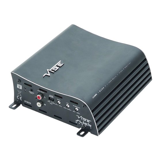
- Page 12 Slick Bass 1 TERMINALS AND CONNECTIONS 1. Low level input For connection to any source (head unit) with a low level output. This is your RCA output from the source (headunit) 2. Remote control input socket Used to connect the supplied remote level control. 3.
- Page 13 Slick Bass 1 SINGLE SUBWOOFER WIRING CONFIGURATION 2 OHM MINIMUM DUAL SUBWOOFER WIRING CONFIGURATION 4 OHM MINIMUM 4 OHM MINIMUM...
- Page 14 Note: By using the crossovers correctly you will not only lengthen the life of your speakers but you will also get better performance from them. To optimise your setup seek the advise of a professional installation engineer or visit your local VIBE audio dealer.
-
Page 15: Specifications
SPECIFICATIONS Slick Slick Slick Slick Stereo 2 Stereo 4 Bass 1 Channel 5 2 Channel 4 Channel Mono Bass Amp 5 Channel 2.3” (58mm) 2.3” (58mm) 2.3” (58mm) 2.3” (58mm) 7.9” (201mm) 10.3” (261mm) 8.8” (218mm) 16.5” (420mm) 6.4” (163mm) 6.4”...
Need help?
Do you have a question about the Slick Stereo 2 and is the answer not in the manual?
Questions and answers