
Related Manuals for Toa RX-7-164


Summary of Contents for Toa RX-7-164
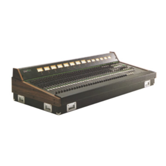
- Page 1 All manuals and user guides at all-guides.com Operating Instruction Manual TOA MIXING CONSOLE Model RX-7-164, RX-7-248, RX-7-328 TOA ELECTRIC CO., LTD. KOBE, JAPAN...
-
Page 2: Table Of Contents
Module Replacement ........33 Dimensional Diagrams (RX-7-164, RX-7-248, RX-7-328, RXM-7-25, RXM-7-35, RXM-7-43, RPS-7). -
Page 3: Precautions
All manuals and user guides at all-guides.com Precautions 1. Power Supply Unit (RPS-7) The RPS-7 is separate from the console. If the power switch on the RPS-7 is turned "on" without a connection between the RPS-7 and the board using the accessory cable packed in the RPS-7, power is not supplied to the board. -
Page 4: General Description
All manuals and user guides at all-guides.com General Description TOA's RX-7 is a modular 16, 24 or 32 input channel, 4 group output, 4 to 8 program output mixing console. It is designed to meet a wide variety of requirements in professional sound reinforcement and recording applications. -
Page 5: Features
All manuals and user guides at all-guides.com Features INPUT MODULE 1. Phantom Power ON/OFF switch. 2. TRIM gain control offers extremely convenient operation when used in conjunction with INPUT LEVEL switch. 3. MID-EQ is peaking equalization, and its center frequency can be set by a continuously variable frequency control knob. - Page 6 All manuals and user guides at all-guides.com PROGRAM MODULE 1. Group 1, 2, 3 and 4 controls pick up the signal from the four group out busses and assign them to the program output. The program output is therefore suitable for feeding the signal to the house sound system.
-
Page 7: Specifications & Characteristics
All manuals and user guides at all-guides.com Specifications & Characteristics GENERAL SPECIFICATIONS RX-7-164, RX-7-248 AND RX-7-328 Frequency Response (Measurement of source impedance 150 VU Meters (0VU = +4dB* output) ohms) RX-7-164 +0dB, -0.5dB; 50Hz to 20kHz +0dB, -2.0dB; 20Hz to 30 kHz 4 large, illuminated meters;... -
Page 8: Input & Output Specifications
All manuals and user guides at all-guides.com Input & Output Specifications RX-7 INPUT CHARACTERISTIC Actual For Use Input Level* Level Connection Load With Sensitivity* Connector** Switch Impedance Nominal Nominal MAX. Before Clip INPUT -60dBm 1.2k ohms -80dB (0.08mV) -60d B (0.78mV) to -30dB (25mV) -26dB (39mV) to +4dB (1.23V) 50 to 600 XLR-3-31... -
Page 9: Level Diagrams & Characteristics Diagrams
All manuals and user guides at all-guides.com Level Diagrams (Fig. 1) Characteristics Diagrams EQUALIZER CURVES FILTER CURVES (Fig. 2) — 8 —... -
Page 10: Ipm-7 (Input Module)
All manuals and user guides at all-guides.com Input Module (IPM-7) 1. XLR type INPUT connector is balanced, transformer-isolated and accepts low impedance sources from -60dB to +10dB. Proper adjustment of both the INPUT LEVEL Switch and TRIM Knob make it possible to provide the optimum setting for each input. 2. - Page 11 19. CUE pushbutton assigns the post-EQ, pre-fader signal to the cue bus for monitoring with headphones, monitor speakers, and/or the cue VU meter. A separate cue VU meter is provided on the RX-7-328, but the cue and talkback VU meter is combined and is switchable on the RX-7-164 and RX-7-248. — 10 —...
-
Page 12: Gfm-7 (Group/Foldback M O D U L E )
VU meter. A separate cue VU meter is provided on the RX-7-328, but the cue and talkback VU meter is combined and is switchable on the RX-7-164 and RX-7-248. 13. GROUP ON/OFF pushbutton connects or disconnects the signal to the GROUP out and group out bus. -
Page 13: Gem-7 (Group/Echo Module)
VU meter. A separate cue VU meter is provided on the RX-7-328, but the cue and talkback VU meter is combined and is switchable on the RX-7-164 and RX-7-248. 13. GROUP ON/OFF pushbutton connects or disconnects the signal to the GROUP out and group out bus. -
Page 14: Pgm-7 (Program Module)
All manuals and user guides at all-guides.com Program Module (PGM-7) Each program module incorporates two program output channels (programs A and B) and each program channel can be controlled independently. 1. PROGRAM OUTPUT B connector (XLR type) is balanced, transformer-isolated. The nominal level and impedance are +4dB and 600 ohms, respectively. -
Page 15: Phm-7 (Phones M O D U L E )
All manuals and user guides at all-guides.com Phones Module (PHM-7) 1. AIR MONITOR (Ceiling Microphone) inputs, XLR type connectors (L and R) are balanced, transformer-isolated. The nominal levels and impedances are —70dB and 600 ohms, respectively. 2. PHONES OUT jacks (L and R) are unbalanced. The nominal levels and impedances are +4dB and 10k ohms, respectively. -
Page 16: Tbm-7 (Talkback Module)
All manuals and user guides at all-guides.com Talkback Module (TBM-7) 1. TALKBACK OUT connector (XLR type) is balanced, transformer-isolated, and its nominal level and impedance are +4dB and 600 ohms, respectively. The talkback output includes the oscillator/pink noise generator signal or talkback mic input, depending on the switch status on the module. -
Page 17: Psm-7 (Power Supply M O D U L E )
All manuals and user guides at all-guides.com Power Supply Module (PSM-7) 1. DC POWER INPUT connector accepts DC power from the power supply unit (RPS-7). The PSM-7 is connected to the RPS-7 with an accessory umbilical cable. The power switch on the RPS-7 will not turn on without this connection between the RPS-7 and PSM-7. -
Page 18: Meter Panel (Rxm-7-25, Rxm-7-35, Rxm-7-43)
All manuals and user guides at all-guides.com Meter Panel (RXM-7-25, RXM-7-35, RXM-7-43) METER PANEL (RXM-7-25) (Fig. 11) 1. Group I/Program 1 VU Meter An illuminated VU meter provides a visual indication of either Group 1 output level (Post Group 1 Master Fader) or Program 1 output level (Post Program 1 Master Control), depending on the position of the adjacent selection switch. - Page 19 All manuals and user guides at all-guides.com 10. VU meter selector switch (Foldback 1 or Echo 1) 11. Foldback 2/Echo 2 VU meter An illuminated VU meter provides a visual indication of either Foldback 2 output level, (Post Foldback 2 Master Volume Control) or Echo 2 output level (Post Echo 2 Master Volume Control), depending on the position of the adjacent selector switch.
- Page 20 All manuals and user guides at all-guides.com METER PANEL (RXM-7-35) (Fig. 12) 1. Group 1 VU Meter (Group 1 output level) 2. Group 2 VU Meter (Group 2 output level) 3. Group 3 VU Meter (Group 3 output level) 4. Group 4 VU Meter (Group 4 output level) 5.
- Page 21 All manuals and user guides at all-guides.com METER PANEL (RXM-7-43) (Fig. 13) 1. Group 1 VU Meter (Group 1 output level) 2. Group 2 VU Meter (Group 2 output level) 3. Group 3 VU Meter (Group 3 output level) 4. Group 4 VU Meter (Group 4 output level) 5.
-
Page 22: Rps-7 (Power Supply Unit)
All manuals and user guides at all-guides.com Power Supply Unit (RPS-7) In order to minimize hum, and also to break up the total weight and to protect the body of the RX-7 from rough transportation, RX-7 series mixers are equipped with a separately packaged power supply unit (RPS-7). -
Page 23: General Information On Using The Mixing Console
All manuals and user guides at all-guides.com General Information on using the mixing console * Impedance Generally speaking, there are two rules to follow when connecting equipment outputs to the inputs of other equipment. 1. Try to properly match the impedances of the outputs and inputs. 2. - Page 24 All manuals and user guides at all-guides.com * Ground loops AC ground is provided to the RX-7 and all associated equipment, and this may cause an increase in hum noise if care is not taken in connecting other equipment to the mixer. This is because a ground loop is made through the shields of the connection cable and the AC line as shown in Fig.
-
Page 25: Function Details
All manuals and user guides at all-guides.com Function Details The RX-7 is a sophisticated mixer with many functions. Details on important functions are shown below in order for you to get the best operation and performance and also to avoid mistakes in operation. - Page 26 All manuals and user guides at all-guides.com *Input Level Switch & Trim Control In accordance with the input signal level, the combination of the Input Level Switch and Trim Control on each input module helps establish the input fader at an easy-operation position. When the Peak level indicator (the red LED) remains on or flashes occasionally, fully attenuate the trim control.
- Page 27 All manuals and user guides at all-guides.com * Equalizers The RX-7 equalizers provide low and high frequency shelving and mid-range peaking, both boost and attenuation. The mid-range EQ center frequency can be set at any frequency between 200Hz and 5kHz with a continuously variable frequency knob. Fig.
- Page 28 All manuals and user guides at all-guides.com INSTRUMENT EQUALIZATION CHART Acoustic guitar Bass strings resonate between 70 to 120Hz, body around 300Hz. Avoid boosting these to stop feedback. 3kHz and 5kHz give great "clarity". Resonances differ— depending on type. Good full sounds around Electric guitar 300 to 500Hz.
- Page 29 All manuals and user guides at all-guides.com * Equalizer IN/OUT Switch Precise equalizer adjustment can be made while comparing the equalized sound effect with the flat sound by use of the Equalizer IN/OUT switch. *Foldback 1, 2 and Echo 1, 2 The block diagram indicates the overall signal flow of the FB and Echo circuits.
- Page 30 All manuals and user guides at all-guides.com *RX-7 Signal Flow The overall signal flow of the RX-7, from input to output, is shown below. (Fig. 21) — 29 —...
- Page 31 For this purpose, air monitor (ceiling microphones) inputs are provided on the phones module and incorporate 48V DC phantom powering circuit for condenser microphones (e.g. TOA RD- 15C microphone).
-
Page 32: Connection Examples I
All manuals and user guides at all-guides.com Connection Example I Portable Entertainment Sound Reinforcement Set-Up TOA's RX-7 consoles are designed to help out when Accessory Send outputs. Other output terminals can be you're out on the road. We're sure you'll find just the right... - Page 33 All manuals and user guides at all-guides.com Connection Example II Multi-Track Recording or Track-Down The TOA RX-7 series of mixing consoles allows better processing equipment connections can be made via recordings as well as better concerts. For multi-track Group Accessory Send/Receive jacks. The PGM output...
-
Page 34: Module Replacement
All manuals and user guides at all-guides.com Module Replacement How to remove modules 1. Remove the armrest from the cabinet in the following manner. *Put both hands under the armrest and lift it straight up to remove. (Fig. 24) 2. Loosen the two captive screws on the front of the meter panel and lift panel straight up. (Fig. - Page 35 All manuals and user guides at all-guides.com Use fingers to lift up the module. Insert each module by fitting it into the guide hole in the base plate of the console unit. (Fig. 26) 3. Remove the two binding screws on each module. Put your fingers in the two holes on the top and bottom of the module and lift the module straight up to remove it from the cabinet.
-
Page 36: Dimensional Diagrams (Rx-7-164, Rx-7-248, Rx-7-328, Rxm-7-25, Rxm-7-35, Rxm-7-43, Rps-7)
All manuals and user guides at all-guides.com Dimensional Diagrams RX-7-164 APPEARANCE (Fig. 27) 9. VU Meters for Foldback and Echo (Switchable) 1. Input Modules (IPM-7) 10. VU Meter for Cue and Talkback (Switchable) 2. Group/Foldback Modules (GFM-7) 11. Foldback Outputs 3. - Page 37 All manuals and user guides at all-guides.com RX-7-248 APPEARANCE (Fig. 28) 10. VU Meter for Foldback and Echo Outputs 1. Input Modules (IPM-7) (Switchable) 2. Group/Foldback Modules (GFM-7) 11. VU Meter for Cue and Talkback (Switchable) 3. Group/Echo Modules (GEM-7) 12.
- Page 38 All manuals and user guides at all-guides.com RX-7-328 APPEARANCE (Fig. 29) VU Meter for Foldback 1 Input Modules (IPM-7) VU Meter for Foldback 2 Group/Foldback Modules (GFM-7) VU Meter for Echo 1 Group/Echo Modules (GEM-7) VU Meter for Echo 2 Program Modules (PGM-7) VU Meter for Cue Phones Module (PHM-7)
- Page 39 All manuals and user guides at all-guides.com RXM-7-25 APPEARANCE (Fig. 30) Armrest VU Meter for Cue and Talkback (Switchable) Bus Chassis Meter Side Panel Wood Side Panel Foldback Outputs Metal Side Panel Group Outputs Main Rear Panel Echo Send Outputs Meter Panel Base VU Meters for Group and Program Outputs...
- Page 40 All manuals and user guides at all-guides.com RXM-7-35 APPEARANCE (Fig. 31) Armrest VU Meter for Foldback and Echo Outputs Bus Chassis (Switchable) Wood Side Panel VU Meter for Cue and Talkback (Switchable) Metal Side Panel Meter Side Panel Main Rear Panel Foldback Outputs Meter Panel Group Outputs...
- Page 41 All manuals and user guides at all-guides.com RXM-7-43 APPEARANCE (Fig. 32) 11. VU Meter for Echo 1 12. VU Meter for Echo 2 1. Armrest 13. VU Meter for Cue 2. Bus Chassis 14. VU Meter for Talkback 3. Wood Side Panel 15.
- Page 42 All manuals and user guides at all-guides.com RPS-7 APPEARANCE (Fig. 33) 1. AC Fuse Holder 2. Power On/Off Indicator 3. Power On/Off Switch 4. DC Power Output Connector 5. Ground Terminal 6. AC Inlet — 41 —...
-
Page 43: Block Diagram
All manuals and user guides at all-guides.com Block Diagram (Fig. 34) — 42 —... - Page 44 All manuals and user guides at all-guides.com TOA ELECTRIC CO., LTD. KOBE, JAPAN Printed in Japan 133-02-476-20...
Need help?
Do you have a question about the RX-7-164 and is the answer not in the manual?
Questions and answers