
Related Manuals for Toa RX-31C


Summary of Contents for Toa RX-31C
- Page 1 All manuals and user guides at all-guides.com Operating Instruction Manual TOA MIXING CONSOLE Model RX-31C TOA ELECTRIC CO., LTD. KOBE, JAPAN...
-
Page 2: Table Of Contents
3. Phantom Power Supply The RX-31C incorporates a 48V DC Phantom Power circuit. If phantom power is required, the Phantom ON/OFF switch on each input channel for which phantom power is required should be "on". -
Page 3: General Description
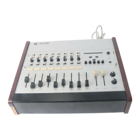
All manuals and user guides at all-guides.com General Description The RX-31C is an eight input, one program output and one line output mixer, designed especially for sound reinforcement systems in auditoriums, churches and similar applications. Each input channel is transformer isolated and accepts either a low impedance microphone or a high level source. -
Page 4: Front Panel
All manuals and user guides at all-guides.com Front Panel Phantom Power (48V DC) Switches- LED Peak Meter The individual channels' switches should The LED peak meter with 12 sections be "on" when one or more condenser calibrated in 3dB steps, responds instan- microphones are connected, and the taneously to the program output level. -
Page 5: Rear Panel
All manuals and user guides at all-guides.com Rear Panel Program Output Connector (PGM OUT). The Program Output Connector is bal- anced and transformer isolated. The nominal signal level and impedance are +4dB and 600 ohms, respectively. Line Output Connector (LINE OUT) Input Channel Connector(s) (INPUT) The Line Output Connector is balanced The XLR connectors are balanced,... -
Page 6: Rack Mounting Instructions
All manuals and user guides at all-guides.com Rack Mounting Instructions The RX-31C is designed to be used either console style or to be rack-mounted, using a pair of optional brackets (model MB-701). The following procedure should be followed to rack-mount the mixer using the MB-701. -
Page 7: Input Connections
It goes without saying that not only input and output impedance matching but also level matching should be taken into consideration. Each input channel of the RX-31C is provided with an input TRIM control, so the usable signal level range is very wide. Input impedances and levels are shown in the following table. -
Page 8: Connection Examples
All manuals and user guides at all-guides.com Connection Examples DISK PLAYER WITH A MM CARTRIDGE Input channels 1-8 should be connected with low impedance (50-ohm~600-ohm) microphones WIRELESS TUNER when the MIC/LINE selector switch SUCH AS WT-02, is set to the MIC position. At LINE WT-06 position the impedance of the in- puts changes to 1lk ohms, so that... -
Page 9: Block And Level Diagram
All manuals and user guides at all-guides.com Block and Level Diagrams RX-31C BLOCK DIAGRAM LEVEL DIAGRAM – 8 –... -
Page 10: Avoiding Ground Loops
Therefore, this should be checked and determined for each installa- tion. Care must be taken that when the RX-31C is mounted in a metal cabinet, the chassis ground line of other equipment is connected through the cabinet. -
Page 11: E F F E C T I V E M I X I N
If the impedances and levels do not match, mixing will be very difficult and the S/N ratio will also be adversely affected. Each input channel of the RX-31C is provided with a TRIM control. Thorough understanding of the function of a TRIM control will make mixing easily. -
Page 12: S P E C I F I C A T I O N
All manuals and user guides at all-guides.com Specifications Frequency Response: +0dB, -3dB. 15Hz~ 30kHz (Measurement of B&K Type 2010 output imp. 5 Total Harmonic Distortion: 0.1%, +4dBm at 1kHz Ham and Noise (Rg = 150 ohms): —130dBm Equivalent Input Noise (20Hz~ 20kHz) —132dBm Equivalent Input Noise (IHF A Weighted) —88dBm ALL FADERS DOWN (IHF A Weighted) —73dBm PGM FADER AT NOMINAL AND ALL INPUT FADERS DOWN... -
Page 13: C H A R A C T E R I S T I C D I A G R A M
All manuals and user guides at all-guides.com Characteristic Diagrams FREQUENCY RESPONSE HPF & LPF CHARACTERISTICS OUTPUT EQ CHARACTERISTIC Appearance *Dimensions with a bracket – 12 –... - Page 14 All manuals and user guides at all-guides.com TOA ELECTRIC CO., LTD. KOBE, JAPAN Printed in Japan 133-02-489-??
Need help?
Do you have a question about the RX-31C and is the answer not in the manual?
Questions and answers