Advertisement
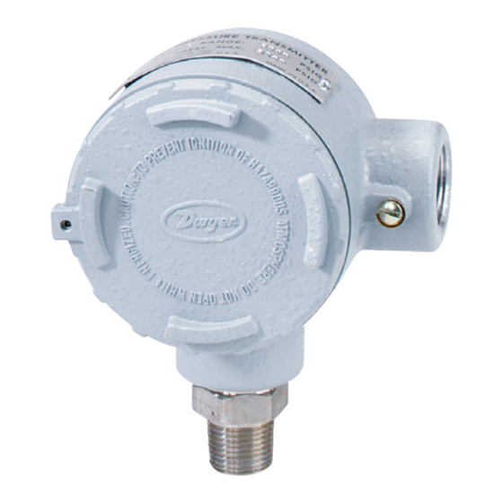
The Series 634ES Pressure Transmitter senses a single
air, compatible gas or liquid pressure and converts it into
a standard 4-20 mA output signal. Ranges are available
from 0-10 through 0-6000 psi. All models are field
adjustable so any range within these limits can be
achieved by recalibration using the easily accessible
span and zero potentiometers.
Positive pressure can be measured within an accuracy of
±0.5% of span. The Series 634ES uses an isolated
piezoresistive pressure sensor to produce a resistance
change across a wheatstone bridge. The signal is condi-
tioned and converted into a 4-20 mA output signal.
For applications requiring direct pressure or percent of
full span readings, the optional A-701 digital readout
makes an ideal companion device, providing a bright .6"
high, 3-1/2˝ digit LED and supplying power to the Series
634ES Transmitter.
Series 634ES Models and Ranges in PSI (bar)
Model Number
As Stocked
Min. Range
634ES-0
10 (.69)
30 (2.07)
634ES-1
634ES-2
50 (3.45)
634ES-3
100 (6.9)
634ES-4
200 (13.8)
300 (20.7)
250 (17.2)
634ES-5
350 (24.1)
634ES-6
500 (34.5)
634ES-7
1000 (69)
600 (41.4)
634ES-8
2000 (138)
4000 (276)
2500 (172)
634ES-9
DWYER INSTRUMENTS, INC.
P.O. BOX 373 • MICHIGAN CITY, INDIANA 46361, U.S.A.
Series 634ES Pressure Transmitter
Specifications - Installation and Operating Instructions
Max. Range
Max Pressure
10 (.69)
20 (1.38)
30 (2.07)
20 (1.38)
40 (2.76)
60 (4.14)
40 (2.76)
60 (4.14)
100 (6.9)
60 (4.14)
120 (8.3)
200 (13.8)
100 (6.9)
250 (17.2)
400 (27.6)
350 (24.1)
500 (34.5)
600 (41.4)
1000 (69)
1250 (86)
2000 (138)
1250 (86)
2500 (172)
4000 (276)
6000 (414)
7500 (517)
(3) #10-32 x 1/4 [6.35] DP HOLES
EQUALLY SPACED ON A 2-1/2 [63.50] B.C.
2-1/2 [63.50]
TYP
1-11/16
[42.86]
5-5/16
[134.94]
1/2NPT
1/4NPT
PHYSICAL DATA
GENERAL
Maximum Pressure: See chart on this page.
Wetted Parts: 316, 316L Stainless Steel.
Housing: Designed to meet NEMA-4X.
ELECTRICAL
Power Supply: 12.3-35 VDC-2 wire.
Output Signal: 4-20 mA DC (limited at 38 mA DC).
Loop Resistance: 0 - 1100 ohms from 12.3 to 35 VDC.
Current Consumption: DC: 38 mA max.
MATERIALS
Housing: Cast aluminum; textured gray polyurethane
finish.
Pressure Connection: Stainless Steel.
MECHANICAL
Weight: 1 lb., 12 oz. (.8 kg).
Span and Zero Adjustments: Protected potentiome-
ters, located in auxiliary housing.
Pressure Connection:
NPT.
PERFORMANCE AT 70°F (21.1°C)
Zero Output: 4 mA DC.
Full Span: 16 mA DC.
Accuracy: ±0.5% of span.
Warm-up Time: 10 minutes.
STABILITY/ENVIRONMENTAL
Operating Temperature: 20 to 120˚F (- 6.7 to 48.9˚C).
Thermal Errors: ± 0.02%/˚F typical.
Stability: 1% F.S./yr.
STANDARD ACCESSORIES
(3) "Z" mounting brackets.
(3) 10-32 x 4" RH machine screws.
Phone: 219/879-8000
Fax: 219/872-9057
Bulletin E-69ES
1-9/16
[39.69]
3/4 NPT
03-3/8 [85.73]
1/16 [1.59]
25/32 [19.84]
2-7/8 [73.03]
R
=
Vps-12.3V
L max
20 mA
1/4˝ female NPT x 1/2˝ male
www.dwyer-inst.com
e-mail: info@dwyer-inst.com
Lit-By Fax: 888/891-4963
Advertisement
Table of Contents

Subscribe to Our Youtube Channel
Related Manuals for Dwyer Instruments 634ES Series


Summary of Contents for Dwyer Instruments 634ES Series
- Page 1 6000 (414) 634ES-9 7500 (517) STANDARD ACCESSORIES (3) “Z” mounting brackets. (3) 10-32 x 4” RH machine screws. DWYER INSTRUMENTS, INC. Phone: 219/879-8000 www.dwyer-inst.com P.O. BOX 373 • MICHIGAN CITY, INDIANA 46361, U.S.A. Fax: 219/872-9057 e-mail: info@dwyer-inst.com Lit-By Fax: 888/891-4963...
- Page 2 Bulletin E-69ES Page 2 Series 634ES Pressure Transmitter Specifications - Installation and Operating Instructions INSTALLATION LOCATION: Select a location where temperature of the unit will be between 20°F and 120°F. Distance from the receiver is limited only by total loop resistance. See “Electrical Connections.”...
- Page 3 Bulletin E-69ES Page 3 Series 634ES Pressure Transmitter Specifications - Installation and Operating Instructions WIRE LENGTH - The maximum length of wire connect- ing transmitter and receiver is a function of wire size and receiver resistance. Wiring should not contribute more 634ES POWER than 10% of receiver resistance to total loop resistance.
- Page 4 4 and 20 mA respectively. 7. Remove the milliameter from the current loop and pro- ceed with final installation of the transmitter and receiver. ©Copyright 2002 Dwyer Instruments, Inc. Printed in U.S.A. 6/02 FR# 01-440577-04, Rev. 3 DWYER INSTRUMENTS, INC.
Need help?
Do you have a question about the 634ES Series and is the answer not in the manual?
Questions and answers