Table of Contents
Advertisement
Quick Links
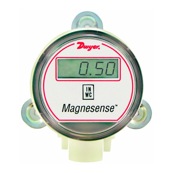
The Series MS Magnesense
Transmitter is an extremely versatile transmitter for monitoring
pressure and air velocity. This compact package is loaded with
features such as: field selectable English or metric ranges, field
upgradeable LCD display and the ability to select a square root
output for use with Pitot tubes and other similar flow sensors.
Also, a single digital push button simultaneously calibrates
both zero and span reducing installation and setup time. These
features along with exceptional long term performance
enables the Magnesense
®
pressure and air flow applications.
INSTALLATION
Mounting:
The transmitter should be mounted on a vertical surface with
the connections directed down to prevent moisture from enter-
ing either the pressure ports or the electrical cable entry.
Mount the transmitter using #8 x 1/2˝ pan head sheet metal
screws in the mounting flanges. Do not over tighten.
Electrical Connection:
2-Wire Operation:
CAUTION: DO NOT EXCEED SPECIFIED SUPPLY
VOLTAGE RATINGS. PERMANENT DAMAGE
NOT COVERED BY WARRANTY WILL RESULT.
2-WIRE UNITS ARE NOT DESIGNED FOR AC
VOLTAGE OPERATION.
DWYER INSTRUMENTS, INC.
P.O. Box 373 • Michigan City, IN 46361-0373, U.S.A.
Series MS Magnesense
Specifications - Installation and Operating Instructions
®
Differential Pressure
to be the solution for a myriad of
®
Differential Pressure Transmitter
21/32
Ø3-7/16
(16/67)
(Ø87.31)
2-41/64
(67.07)
1/2 NPT
2-11/64
(55.17)
2-9/16
(65.09)
SPECIFICATIONS
Service: Air and non-combustible, compatible gases.
Wetted Materials: Consult Factory.
Accuracy: ±1% @ standard conditions
Stability: ±1% F.S./ year.
Temperature Limits: 0 to 150°F (-18 to 66°C).
Pressure Limits: 1 psi maximum, operation; 10 psi, burst.
Power Requirements: 2-wire, 10 to 35 VDC; 3-wire, 17 to
36 VDC or isolated 21.6 to 33 VAC.
Output Signals: 2-wire, 4 to 20 mA; 3-wire, 0 to 10 V.
Response Time: 300 msec
Pressure Calibration: One Digital push button set both zero &
span simultaneously.
Loop Resistance: Current Output: 0-1250 Ohm max. Voltage
Output: min. load resistance 1 k OhmΩ.
Current Consumption: 40 mA max.
Display (optional): 4 digit LCD.
Electrical Connections: 4-20 mA Units: 2-Wire: European Style
Terminal Block for 16 to 26 AWG; 0-10 V Units: 3-Wire:
European Style Terminal Block 16 to 22 AWG.
Electrical Entry: 1/2˝ NPS Thread.
Accessory: Cable Gland for 5 to 10 mm diameter cable.
Process Connections: 3/16˝ (5 mm) ID tubing. Maximum
OD 9 mm.
Enclosure Rating: NEMA 4X (IP65).
Mounting Orientation: Insensitive to mounting orientation
Weight: 8.0 oz (230 g).
Agency Approvals: CE.
The following standards were used for CE approval:
CENELEC EN 61000-4-2: 2001
CENELEC EN 61000-4-3: 2002
CENELEC EN 61000-4-4: 1995
CENELEC EN 61000-4-5: 2001
CENELEC EN 61000-4-6: 2003
CENELEC EN 61000-4-8: 2001
CENELEC EN 55011: 2003
CENELEC EN 61326: 2002
89/336/EED EMC Directive
Phone: 219/879-8000
Fax: 219/872-9057
Bulletin A-26P
21/32
(16/67)
1/2
29/32
(12.70)
(23.02)
57/64
(22.62)
(3) 3/16 (4.76) HOLES
EQUALLY SPACED ON A
4.115 (104.52) BC
www.dwyer-inst.com
e-mail: info@dwyer-inst.com
Advertisement
Table of Contents

Related Manuals for Dwyer Instruments MS Magnesense Series


Summary of Contents for Dwyer Instruments MS Magnesense Series
- Page 1 VOLTAGE OPERATION. CENELEC EN 61000-4-6: 2003 CENELEC EN 61000-4-8: 2001 CENELEC EN 55011: 2003 CENELEC EN 61326: 2002 89/336/EED EMC Directive DWYER INSTRUMENTS, INC. Phone: 219/879-8000 www.dwyer-inst.com P.O. Box 373 • Michigan City, IN 46361-0373, U.S.A. Fax: 219/872-9057 e-mail: info@dwyer-inst.com...
- Page 2 Bulletin A-26P Page 2 Electrical Connection: The connections to the transmitter are made through a three cir- 2-Wire Operation, continued: cuit European style terminal block. Connect the power and signal leads to the corresponding terminals as shown in Fig. 3. When The connections to the transmitter are made through a two circuit using a DC supply, the positive of the supply should be connected European style terminal block CONN6 located at the bottom of the...
- Page 3 Bulletin A-26P Page 3 Select Operation Mode: The operating modes and ranges are controlled by a shorting jumper on jumper block J2. This jumper block is shown in Fig. 5. FULL SCALE ANALOG OUTPUT Model English Metric MS-X31 10 in w.c. 2 kPa MS-X41 15 in w.c.
- Page 4 Be sure to include a brief description of the problem plus any relevant application notes. Contact customer service to receive a return goods authorization number before shipping. ©Copyright 2007 Dwyer Instruments, Inc. Printed in U.S.A. 1/07 FR# 01-443337-20 Rev.1 DWYER INSTRUMENTS, INC.
Need help?
Do you have a question about the MS Magnesense Series and is the answer not in the manual?
Questions and answers