Table of Contents
Advertisement
Available languages
Available languages
Quick Links
Advertisement
Chapters
Table of Contents
Troubleshooting

Subscribe to Our Youtube Channel
Related Manuals for Optika INSPECTION SYSTEMS Series


Summary of Contents for Optika INSPECTION SYSTEMS Series
- Page 1 INSPECTION SYSTEMS Series INSTRUCTION MANUAL Model IS-01 Version: 1 Issued: 1.0.0...
- Page 2 IS-01 Compact Inspection Video Microscope INSTRUCTIONS This instruction manual is for the operation guide, troubleshooting and maintenance to IS-01 compact Inspection Video Microscope. Please study this manual thoroughly before operating, and keep it with the instrument. The manufacturer reserves the rights to the modifications by technology development. On the basis of operation ensured, technical specifications may be subject to changes without notice Pag.
-
Page 3: Table Of Contents
Contents Hardware 1. Getting Ready Operation Maintenance Components 2. Assembling Assembling Scheme Assembling Steps 3. How to Use Adjust the Focusing Tension Set Illumination Place the Specimen Adjust the Focus Lock the Magnification Use the Button and Interface 4. Troubleshooting 5. -
Page 4: Getting Ready
Getting Ready Operation 1) Do not expose the microscope in the sun directly. The microscope ought to be placed where is dry and clean. Avoid high temperature and violent vibration. 2) As the microscope is a high precision instrument, always operate it with care, and avoid physical shock or crash during the transportation. -
Page 5: Components
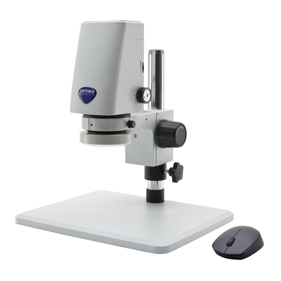
Components Display Microscope body HDMI connector MINI connector USB connector Magnification changer Video button Image button Power switch ringlight Coarse focus knob Microscope stand LED light adjustment knobs Pag. 5... - Page 6 SD card slot Lock for magnification changer Power supply input Pag. 6...
-
Page 7: Assembling
2. Assembling Assembling Scheme Below is the Assembling Scheme to describe how to assemble the components, and the numbers denote the assembling order. Before assembling, make sure there is no dust, dirt or other materials which will disturb it. Assemble carefully and do not scrap any part or touch the glass surface. -
Page 8: Assembling Steps
Assembling Steps 2-2-1 Assemble the extension ring (Fig. 1-2) 1. Unscrew the three screws on the bottom of the stand in order to remove the microscope arm. 2. Install the extension ring on the stand, then reinstall the microscope arm. •... - Page 9 2-2-3Assemble the Microscope Body (Fig. 1. Match the dovetail interface ① of the microscope body with the dovetail groove ② of the focus bracket group, and insert it from top to bottom as the direction shown in the figure. 2. Tighten the M4 inner hexagon screw on the body group ③...
- Page 10 2-2-6 Installing Additional lenses (Fig. 8-9- It is possible to install any of the available additional lenses (0.5x or 1.4x). To do this, please follow these steps: 1. Remove the LED ring light from the bottom of the microscope body. (Fig. 8) Fig.
-
Page 11: How To Use
3. How to Use 3-1 Adjust the Focusing Tension (Fig. 11) 1. To adjust the focusing tension, grip the left knob and rotate the right knob ①. It will be tighten when rotated in clockwise, while loosen in counter-clockwise. Adjust the focusing tension to appropriate position, to prevent the microscope body declining with the bracket when observing, and also make focusing more comfortable... -
Page 12: Place The Specimen
3-3 Place the Specimen (Fig. 14) Put the specimen on the base and let the observation point exactly below the microscope. Fig. 14 3-4 Adjust the Focus (Fig. 15) Rotate the zoom adjustment ring ① to the maximum magnification. Observe the output image, if it is not clear, rotate the focusing knob ②... -
Page 13: Use The Button And Interface
3-6 Use the Button and Interface (Fig. 17- 1. Press the ON-OFF key ① for 3-5 seconds, the indicator ⑦ will turn from orange to green, which means the microscope is starting up. It means the camera is working when the indicator flashes. -
Page 14: Troubleshooting
4. Troubleshooting As the performance of microscope cannot play fully due to unfamiliar operations, the table below can provide some solutions. Problem Cause Solution 1) Stain or dust is observed in the Stains have accumulated on the Clean the specimen. video. -
Page 15: Optical Data
5. Optical Data Objective Optical Magnification On-Screen Horizontal Field of Vertical Field of W.D. Magnification View (mm) View (mm) (mm) 0.35x 8.4x 0.5x 18.2 11.2 0.75x 12.12 0.5x 1.5x 6.06 3.72 4.54 2.5x 3.64 2.24 0.7x 16.8x 1.5x 6.06 4.55 3.03 1.86 2.27... -
Page 16: Overview
6. Overview Software start and quit 6.1.1 Software Start Click the icon application in the main menu to start. 6.1.2 Software Quit Click the background button, all opened software in android system will be appeared. If need to quit, just click the exit button “X” in the top right corner of this software. Or gently swipe to the left or right to exit the program. Pag. -
Page 17: Main Commands
Main Commands 6.2.1 Command introduction Start the program. Once started the program shows the following screen: 6.2.2 Commands icon introduction A brief introduction to the current default icons: : Local browse : Colour and exposure adjustment : Drawing mark tool : White balance lock : WDR Pag. - Page 18 : WiFi output hotkeys : USB output hotkeys : Settings : Image / video switch hotkeys : Image zoom Pag. 18...
-
Page 19: Operation Instructions
Operation Instructions Local browse Click on the button in the left menu bar, will jump to the local gallery. Click on the corresponding folder to view and edit the pictures and videos files: (delete images, colour effect transformation, etc.) Colour and exposure adjustment Click on the button in the left menu bar, will pop up a translucent view window in the main screen, including exposure adjustment and colour adjustment, as shown in the figure:... -
Page 20: Exposure Adjustment
7.2.1 Exposure Adjustment Exposure adjustment region select exposure mode, Manual Automatic exposure (AutoExposureLock “OFF” “ON”) Exposure Compensation Time ,Gain ,Integration 7.2.2 Colour Adjustment Colour adjustment region affects the visual contrast adjustment under the different content through the microscope. Colour adjustment includes brightness , contrast saturation , chrominance... - Page 21 Click on “Edit” and a new window appears: Now put a ruler or a known reference under the microscope and focus. Click on “Add”: Pag. 21...
- Page 22 A new window will appear: Move the red marker on the ruler and then click on “Name” Pag. 22...
- Page 23 An input dialog will appear where the user must input the actual magnification: Insert the magnification (e.g. 0,7x) and click on “Next”. Another input dialog will prompt to insert the length of the red marker (e.g. 12 mm) Pag. 23...
- Page 24 Click on “DONE”. You will return to the previous dialog. Now select the unit (µm or mm) At the end of all the operations click on “Calculate”. A dialog will appear: Pag. 24...
-
Page 25: Drawing Mark Tool
Press “OK” and the first calibration point has been saved. Now repeat all these steps for each magnification of the microscope. When all the magnifications will be calibrated, the calibration list will be available: Before performing any measurement, it is important to open the related calibration according to the magnification in use. -
Page 26: Awb (Automatic White Balance)
By clicking the line with mark , or character colour ,another option window will appear showing a colour palette with six colours (yellow, black, white, green, red and blue) By selecting one of these colours will change the colour of the selected item. When use image function, the user can save the marked picture into the local folder along with the image (the marked video will not be saved when recording). -
Page 27: Setting Button
change to , and there is a prompt message for opening the WDR function in the center of the screen WDR function is active WDR function is not active Setting Button To open the setting function, click on button: a translucent window appears as shown: Pag. -
Page 28: Image Real-Time Transmission
Setting module includes Resolution, Frame Rate and Transmission mode. The Resolution has 4 options, respectively: 2688*1520, 1920*1080, 1280*720, 672*376. The Frame Rate value can be selected among 0FPS / 15FPS / 30FPS. The Transmission mode has two options: WiFi and USB transmission Image real-time transmission 7.8.1 WiFi transmission The software can not only capture and display the images in local, but also can do real-time transmission by... - Page 29 Open the portable WLAN hotspot option 2. In case of an external WiFi hotspots, you may need to open the system Settings of WLAN option, even on the need to connect the WiFi. For further details please refer to the Step 2: Step 2: External WiFi hotspot Open the “WLAN”...
-
Page 30: Usb Transmission
Choose the shared network after “WLAN”opened. Now open or WiFi shortcut key on the left menu bar, click on in Settings: a string of IP address will appear External devices through player software can directly enter the IP address in input field, then click play, the devices can get synchronized images as Inspection System. -
Page 31: Image / Video Switch
or click on the shortcut button on the left menu bar, and then open the installed software in receiver device, choose the official version of the video capture program AMCap software, now you can use real-time image transmission function. Image / Video Switch 7.9.1 Image function Choose the image button in Image / Video selection box . -
Page 32: Zoom Picture
Finish Recording 7.10 Zoom Picture You can enlarge the picture when browsing. This function is done through the bar-type control , by moving from left to right the blue dot. While performing measurement, zoom function has to be set at its minimum: zooming the image will result in errors during measurements. -
Page 33: Troubleshooting
8 Troubleshooting As the performance of software cannot play fully due to unfamiliar operations, the table below can provide some solutions. Problem Cause Solution 1) Clicking on WiFi button has Hotspot sharing not open Open the hotspot sharing in no effect and does not settings (refer to step 1) appear the IP address. - Page 34 Serie INSPECTION SYSTEMS MANUALE DI ISTRUZIONI Modello IS-01 Versione: 1 Issued: 1.0.0 Pag. 34...
- Page 35 IS-01 Video Microscopio da Ispezione Compatto ISTRUZIONI Questo manuale di istruzioni si riferisce alla guida operativa, alla risoluzione dei problemi e alla manutenzione del Video Microscopio da Ispezione Compatto IS-01. Si prega di studiare attentamente questo manuale prima di utilizzare lo strumento e di tenerlo a disposizione vicino allo stesso. Il produttore si riserva i diritti sulle modifiche mediante lo sviluppo della tecnologia.
- Page 36 Sommario Hardware 1. Preparazione 1.1 Operazioni 1.2 Manutenzione 1.3 Componenti 2. Assemblaggio 2.1 Schema di assemblaggio 2.2 Procedura di assemblaggio 3. Uso del microscopio 3.1 Regolazione della tensione di messa a fuoco 3.2 Impostazione dell’illuminazione 3.3 Posizionare il campione 3.4 Regolazione della messa a fuoco 3.5 Blocco dell’ingrandimento 3.6 Uso dei tasti e dei connettori 4.
-
Page 37: Preparazione
Preparazione Operazioni 1) Non esporre il microscopio a luce solare diretta. Il microscopio deve essere posizionato in un luogo asciutto e pulito. Evitare alte temperature e vibrazioni violente. 2) Il microscopio è uno strumento di precisione; utilizzarlo sempre con cura, evitare urti ed impatti bruschi ed evitare scossoni durante il trasporto. -
Page 38: Componenti
Componenti Monitor Corpo del microscopio Porta HDMItor Porta MINI USB Porta USB Variatore di ingrandimento Tasto Video Illuminatore Tasto Camera circolare LED Accensione Base del Manopola di microscopio messa a fuoco Manopole regolazione luminosa del LED Pag. 38... - Page 39 Fessura SD card Blocco per variatore di ingrandimento Connettore Alimentatore Pag. 39...
-
Page 40: Assemblaggio
2. Assemblaggio Schema di assemblaggio Di seguito viene indicato lo schema di assemblaggio, per descrivere come montare i componenti; i numeri indicano l’ordine di assemblaggio. Prima del montaggio, assicurarsi che non ci sia polvere, sporcizia o altri materiali che possano disturbare. -
Page 41: Procedura Di Assemblaggio
Procedura di Assemblaggio 2-2-1 Montaggio dell’anello di prolunga (Fig. 1- 1. Svitare le tre viti poste sotto la base del microscopio per rimuovere il braccio del microscopio. 2. Montare l’anello di prolunga sulla base, quindi rimontare il braccio del microscopio. •... - Page 42 2-2-3 Montare il corpo del Microscopio (Fig. 1. Allineare la coda di rondine ① del corpo del microscopio alla coda di rondine ② del braccio del microscopio ed inserirlo dall’alto (come mostrato in figura). 2. Serrare la vite M4 nel corpo del microscopio ③...
- Page 43 2-2-6 Montare le lenti addizionali (Fig. 8-9- E’ possibile usare una qualsiasi delle lenti addizionali disponibili (0.5x o 1.4x). Per fare ciò, seguire la procedura: Rimuovere l’illuminatore circolare dalla parte inferiore del microscopio. (Fig. 8) Fig. 8 Usando cacciavite brugola dotazione, allentare viti...
-
Page 44: Uso Del Microscopio
3. Uso del microscopio 3-1 Regolazione della tensione di messa a fuoco (Fig. 11) 1. Per regolare la tensione di messa a fuoco, tenere ferma la manopola di sinistra e ruotare la manopola destra ①. Per aumentare la tensione ruotare in senso orario, per diminuirla ruotare in senso antiorario. -
Page 45: Posizionare Il Campione
3-3 Posizionare il campione (Fig. 14) Posizionare il campione sulla base e trovare il punto esatto per l’osservazione sotto il microscopio. Fig. 14 3-4 Regolazione della messa a fuoco (Fig. 1. Ruotare l’anello variatore ① ingrandimento Massimo ingrandimento. 2. Osservare l’immagine a monitor. Se non fosse nitida ruotare la manopola di messa a fuoco ②... -
Page 46: Uso Dei Tasti E Dei Connettori
3-6 Uso dei tasti e dei connettori (Fig. 17- 1. Premere il tasto ON-OFF ① per 3-5 secondi, Il LED ⑦ passa da arancione a verde, indicando che il microscopio si sta avviando. Quando il LED lampeggia, significa che la telecamera è... -
Page 47: Risoluzione Dei Problemi
4. Risoluzione dei problemi Poiché le prestazioni del microscopio potrebbero non soddisfare completamente a causa di operazioni non familiari, la tabella seguente può fornire alcune soluzioni. Problema Causa Soluzione 1. Sporco o polvere visibili in Sporcizia sul campione Pulire il campione osservazione. -
Page 48: Dati Ottici
5. Dati ottici Obiettivo Ingrandimento ottico Ingrandimento a Campo Visivo Campo Visivo W.D. Monitor Orizzontale (mm) Verticale (mm) (mm) 0.35x 8.4x 0.5x 18.2 11.2 0.75x 12.12 0.5x 1.5x 6.06 3.72 4.54 2.5x 3.64 2.24 0.7x 16.8x 1.5x 6.06 4.55 3.03 1.86 2.27 120x... -
Page 49: Panoramica
6. Panoramica Avvio e Arresto del Software 6.1.1 Avvio del Software Cliccare sull’icona per avviare il software. 6.1.2 Arresto del Software Cliccare sul tasto centrale. Tutte le applicazioni aperte in Android vengono visualizzate. Per chiudere un’applicazione, cliccare sul tasto “X” in alto a destra di ogni finestra. Oppure scorrere a destra o a sinistra la finestra dell’applicazione per terminarla. -
Page 50: Comandi Principali
Comandi principali 6.2.1 Spiegazione dei comandi Avviare il programma. Una volta avviato (l’inizializzazione richiede qualche secondo) il programma mostra la seguente videata: 6.2.2 Spiegazione delle icone Breve spiegazione delle icone: : Cartella locale di salvataggio : Regolazione colore ed esposizione : Strumento disegno : Blocco bilanciamento del bianco : WDR... - Page 51 : Tasto WiFi : Tasto USB : Impostazioni : Tasto Immagine / Video : Zoom immagine Pag. 51...
-
Page 52: Uso Del Software
Uso del Software Cartella di archiviazione Cliccare sul tasto nella parte sinistra della barra del menu, per aprire la cartella di archiviazione locale delle immagini o dei video acquisiti. Cliccare sulla cartella relativa per visualizzare e modificare le immagini o i file video: (elimina immagini, elaborazioni, ecc) Regolazione di Colore e Esposizione Cliccare sul tasto nella parte sinistra della barra del menu, per aprire una finestra... -
Page 53: Regolazione Esposizione
7.2.1 Regolazione Esposizione La finestra di regolazione dell’esposizione consente di selezionare il modo di esposizione, Manuale o Automatico (AutoExposureLock “OFF” or “ON”) , la Compensazione dell’Esposizione ,il Guadagno ,ed il Tempo di Integrazione 7.2.2 Regolazione Colore La finestra di regolazione del colore consente di modificare la visualizzazione dell’immagine proveniente dal microscopio. - Page 54 Cliccare sul tasto “Edit” Appare una nuova finestra. Cliccare su “Edit” e appare una nuova videata: Posizionare un righello o un micrometro oggetto sotto il microscopio e mettere a fuoco. Pag. 54...
- Page 55 Cliccare su “Add”: Appare una nuova finestra. Spostare il marcatore rosso sul righello Pag. 55...
- Page 56 e cliccare su “Name” Appare una finestra di input dove l’operatore deve inserire il nome dell’ingrandimento corrente: Pag. 56...
- Page 57 Inserire il nome dell’ingrandimento (es. 0,7x) e cliccare su “Next”. Appare un’altra finestra di input dove si deve inserire la lunghezza del marcatore appena posizionato sul righello (es. 12 mm) Cliccare su “DONE”. Si viene riportati alla finestra di dialogo precedente. Selezionare l’unità...
- Page 58 Alla fine di tutte queste operazioni cliccare su “Calculate”. Appare questa finestra di dialogo: Premere “OK” ed il primo punto di calibrazione viene salvato. Ripetere tutti i passaggi per tutti gli ingrandimenti del microscopio. Quando tutti gli ingrandimenti saranno calibrati si otterrà un elenco tipo questo: Pag.
-
Page 59: Strumento Disegno
Prima di eseguire una misura, è importante attivare la calibrazione relative all’ingrandimento in uso con il microscopio. Strumento Disegno Sull’immagine visualizzata, l’operatore può avere molte funzioni utili. Queste possono essere attivate cliccando il tasto righello Cliccando su questo tasto nella parte sinistra della barra del menu è possibile utilizzare una serie di funzioni. -
Page 60: Awb (Bilanciamento Automatico Del Bianco)
Selezionando uno di questi colori si modifica il colore di visualizzazione dell’oggetto selezionato. Quando si usa su una immagine, l’utente può salvare l’immagine unitamente a tutte le linee tracciate nella cartella di salvataggio locale (il video con le line tracciate non può essere salvato. Il risultato della tracciatura delle linee può... -
Page 61: Funzione Wdr
Funzione WDR WDR, acronimo per Wide Dynamic Range, comporta che le parti scure e le parti chiare dell’immagine possono essere visualizzate chiaramente nello stesso momento. Quando la funzione WDR è attiva, il sistema migliora la luminosità delle aree scure, specialmente usando uno stereomicroscopio. -
Page 62: Tasto Setting
Funzione WDR non attiva Tasto Setting Per aprire le funzioni di settaggio, cliccare sul tasto : appare una finestra semitrasparente. Il modulo Setting comprende Resolution, Frame Rate e le modalità di Trasmissione. La Resolution ha 4 opzioni: 2688*1520, 1920*1080, 1280*720, 672*376. Il valore di Frame Rate può... - Page 63 Aprire l’opzione “More” in Settings Aprire l’opzione Portable WiFi hotspot 2. In caso di un hotspot WiFi esterno, si deve aprire l’opzione WLAN nelle impostazioni di sistema, anche in caso di connettere il WiFi. Vedere lo Step 2: Step 2: Hotspot WiFi esterno Aprire “WiFi”...
-
Page 64: Trasmissione Usb
Selezionare la rete condivisa dopo avere attivato il WiFi. Ora aprire o cliccare sul tasto WiFi nella parte sinistra della barra del menu, cliccare su in Settings: una tringa con l’indirizzo IP appare Dispositivi esterni con software dedicati possono accedere direttamente all’indirizzo IP nel campo input, quindi cliccare si “play”: i dispositivi verranno sincronizzati al Software Inspection System. -
Page 65: Tasto Immagine / Video
o cliccare il tasto nella parte sinistra della barra del menu, ed aprire il software nel dispositivo ricevente. Selezionare la versione ufficiale del programma di cattura video AMCap software; ora la trasmissione di immagini in tempo reale è possibile. Tasto Immagine / Video 7.9.1 Funzione Immagine Selezionare il tasto Immagine nel campo di selezione Immagine / Video . -
Page 66: Zoom Immagine
Arresto registrazione 7.10 Zoom Immagine Durante il lavoro è possibile effettuare uno zoom sull’immagine proiettata a monitor. Questa funzione è possibile utilizzando il cursore , spostandolo da sinistra a destra. Durante l’esecuzione di misurazioni, lo zoom deve essere tenuto al minimo: lo zoom dell’immagine potrebbe portare ad errori di misurazione. -
Page 67: Risoluzione Dei Problemi
8 Risoluzione dei problemi Poiché le prestazioni del software potrebbero non soddisfare completamente a causa di operazioni non familiari, la tabella seguente può fornire alcune soluzioni. Problema Causa Soluzione 1. Cliccando sul tasto WiFi non Condivisione di hotspot non attiva Attivare condivisione succede nulla e non appare... - Page 68 100 Lauman Lane, Suite A, Hicksville, NY 11801 Tel: (877) 877-7274 | Fax: (516) 801-2046 Email: Info@nyscopes.com www.microscopeinternational.com OPTIKA S.r.l. Via Rigla, 30 - 24010 Ponteranica (BG) - ITALIA Tel.: +39 035.571.392 - Fax: +39 035.571.435 mailto:minfo@optikamicroscopes.com www.optikamicroscopes.com...
Need help?
Do you have a question about the INSPECTION SYSTEMS Series and is the answer not in the manual?
Questions and answers