
Related Manuals for Optika B-350


Summary of Contents for Optika B-350
- Page 1 Ver. 5.0.0 B-350 OPERATION MANUAL GUIDA UTENTE MANUEL D’INSTRUCTIONS MANUAL DE INSTRUCCIONES BEDIENUNGSANLEITUNG OPTIKA MICROSCOPES - ITALY www.optikamicroscopes.com - info@optikamicroscopes.com...
-
Page 2: Table Of Contents
INDEX 1.0 DESCRIPTION pag. 3 2.0 INTRODUCTION pag. 6 3.0 UNPACKING AND ASSEMBLY pag. 7 4.0 USING THE MICROSCOPE pag. 9 4.1 Observation head 4.2 Place the specimen on the stage 4.3 Illumination system settings 4.4 Interpupillary distance 4.5 Focus tension adjustment 4.6 Diopter adjustment 4.7 Condenser 4.8 Numerical aperture setting... -
Page 3: Observation Head
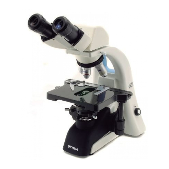
1.0 DESCRIPTION BINOCULAR OBSERVATION HEAD EYEPIECE HEAD LOCKING INTERPUPILLARY SCREW (1) DISTANCE SCALE REVOLVING NOSEPIECE MAIN BODY OBJECTIVE STAGE IRIS DIAPHRAGM CONDENSER FOCUS STOP KNOB BRIGHTNESS ADJUSTMENT FLIP OUT FILTER HOLDER TRANSLATION KNOBS ILLUMINATOR CONDENSER CENTERING SCREWS (2) PHOTO PORT LAMP COVER LIGHT PATH SELECTOR LEVER... - Page 4 1.0 DESCRIPTION DIOPTRIC ADJUSTMENT RING SLIDE CLAMP CONDENSER HEIGHT ADJUSTMENT (4) TENSION ADJUSTMENT KNOB (5) ON-OFF SWITCH FINE FOCUSING KNOB COARSE FOCUSING KNOB FUSE MAINS CABLE ATTACHMENT Page 4...
- Page 5 1.0 DESCRIPTION CONDENSER TURRET (6) PHASE RINGS CENTERING LEVERS (7) Page 5...
- Page 6 2.0 INTRODUCTION This microscope is a scientific precision instrument designed to last for many years with a minimum of main- tenance. It is built to high optical and mechanical standards and to withstand daily use. Optika reminds you that this manual contains important information on safety and maintenance, and that it must therefore be made accessible to the instrument users. Optika declines any responsibility deriving from instrument uses that do not comply with this ma-nual. Safety guidelines This manual contains important information and warnings regarding safety about installation, use and maintenance of the microscope B-350. Please read this manual carefully before using the equipment.
- Page 7 3.0 UNPACKING AND ASSEMBLY The microscope is located in a styrofoam moulded packaging. After removing the adhesive tape from all packaging, lift the top half of the packaging. Pay attention not to drop or damage the optical com- ponents (objectives and eyepieces). Extract the microscope from its packaging with both hands (one around the top arm and one around the base) and place it on a stable surface. Keep it away from solvents, chemical vapors and excessive moisture.
- Page 8 3.0 UNPACKING AND ASSEMBLY Make sure, before you turn the illumination on, that the voltage selector is set to the mains voltage for your region. The power cord should be used only on network sockets equipped with adequate grounding. Contact a technician to check the state of your electrical system. If there is no need to install additional accessories, the instrument is now ready for use. Page 8...
-
Page 9: Illumination System Settings
4.0 USING THE MICROSCOPE Once positioned and installed with the necessary components, the microscope is ready to be used. Your microscope is a laboratory instrument designed to last. Handle it always carefully and avoid abrupt vibrations or shocks. Always disconnect the power cable from the microscope when not in use for long time, while you clean it or when you perform any maintenance. -
Page 10: Diopter Adjustment
4.0 USING THE MICROSCOPE Diopter adjustment Turn the dioptric adjustment ring on the right eyepiece dioptric up to align the bottom with the gradua- ted ring. Turn the coarse focus knob in order to focus the slide with an objective with low magnifica- tion. Adjust the fine focus knob until you obtain a clear and defined picture observing with the right eye, and then repeat the operation with the left dioptric compensation ring and the left eye. When the image appears in focus, choose the necessary objective with the revolving nosepiece. Condenser Raise or lower the condenser through the knob (4) to obtain a clear and uniform illumination of the sample. To center the condenser: completely close the iris diaphragm (3). Using the condenser centering screws (2), move the diaphragm in the center of the field of view. Then gradually expand the diaphragm until it is tangent to the edges of the field of view. If necessary, you can perform an additional adjustment. The condenser is centered when the edges of iris diaphragm are tangent to the field of view. Numerical aperture setting The value of the numerical aperture (N.A.) of the diaphragm is an indication of the contrast of the illu- mination system. Matching the value of illumination system’s N.A. with that of the objective ensures the best results in terms of contrast and image quality. -
Page 11: Additional Filters
4.0 USING THE MICROSCOPE Insert the 10x objective rotating the nosepiece. Rotate the turret of the condenser (6) until you reach the inscription “10”. Loosening the lock screw of the centering telescope, focus on the light ring that you observe. Loosen the locking screws of the phase rings centering levers (7) and slide them forward or backward until the bright light ring is perfectly aligned with the dark ring. Repeat for the other objectives (only as a verification of the correct centering). Once centered with 100x objective, the condenser will be automatically centered also with the other objectives. Phase rings will be centered when you see an image like this: 4.10 Additional filters The blue, yellow and frosted glass filters can be inserted in the flip-out filter holder underneath the condenser. Page 11... -
Page 12: Microscopy Environment
Note: ethanol and ether are highly flammable liquids. Do not use them near a heat source, near sparks or near electric equipment. Use these chemicals in a well ventilated room. - Remember to never wipe the surface of any optical items with your hands. Fingerprints can damage the optics. - Do not disassemble objectives or eyepieces in attempt to clean them. If you need to send the microscope to Optika for maintenance, please use the original packaging. Page 12... - Page 13 6.0 TECHNICAL SPECIFICATIONS Description: Teaching and routine laboratory microscope. Die-cast metal stand, with great stability and ergonomics, intended for transmitted light observation. Illumination: Light source: X-LED type with white LED; brightness adjustment through a potentiome- ter placed in the bottom right side of the stand. LED power 3W, comparable to 30-35W halogen lamp. Average LED lifetime about 50.000 hours. The collecting lens of the illuminator can accommodate additional filters (blue, yellow, frosted). Input voltage: 110/230Vac, 50/60Hz, 0,4/0,8A; Fuse: F2A 250V Maximum power: 7W Observation Brightfield, darkfield, phase contrast, fluorescence modes: Focus: Coaxial coarse and fine (graduated, 0.002mm) focusing system, with focusing stop mechanism (to prevent the objective from hitting the slide). Focus knobs tension is adjustable.
- Page 14 7.0 RECOVERY AND RECYCLING Art.13 Dlsg 25 july 2005 N°151. “According to directives 2002/95/EC, 2002/96/EC and 2003/108/EC relating to the reduction in the use of hazardous substances in electrical and electronic equipment and waste disposal.” The basket symbol on equipment or on its box indicates that the product at the end of its useful life should be collected separately from other waste. The separate collection of this equipment at the end of its lifetime is organized and managed by the producer.
Need help?
Do you have a question about the B-350 and is the answer not in the manual?
Questions and answers