Table of Contents
Advertisement
Quick Links
Advertisement
Table of Contents

Related Manuals for Optika IM-3MET


Summary of Contents for Optika IM-3MET
- Page 1 IM Series INSTRUCTION MANUAL Model IM-3MET Version: Issued: 08, 08, 2017...
-
Page 2: Table Of Contents
Table of Contents Warning Symbols and conventions Safety Information Intended use List of accessories and spare parts Overview Unpacking Assembling Using the microscope Maintenance Troubleshooting Equipment disposal Page 2... -
Page 3: Symbols And Conventions
Warning This microscope is a scientific precision instrument designed to last for many years with a minimum of mainte- nance. It is built to high optical and mechanical standards and to withstand daily use. We remind you that this manual contains important information on safety and maintenance, and that it must therefore be made acces- sible to the instrument users. -
Page 4: List Of Accessories And Spare Parts
List of accessories and spare parts CAT. NO. DESCRIPTION M-625 Eyepiece EWF10x/22mm. M-601 Eyepiece WF15x/16mm. M-602 Eyepiece micrometer EWF10x/22mm. M-005 26x76 mm micrometric slide. Range 1 mm, div. 0,01 mm. M-735 Objective IOS LWD MET PLAN 5x/0,15. M-736 Objective IOS LWD MET PLAN 10x/0,3. M-737 Objective IOS LWD MET PLAN 20x/0,45. -
Page 5: Overview
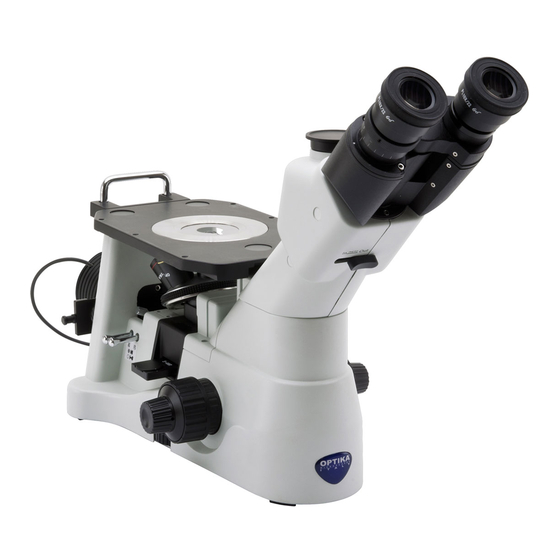
Overview EYEPIECE DIOPTRIC ADJUSTMENT RING TRINOCULAR VIEWING TUBE (FIXED) LAMP HOUSE OBJECTIVE METAL STAGE INSERT LIGHT PATH SELECTOR LEVEL APERTURE DIAPHRAGM MICROSCOPE BODY FIELD DIAPHRAGM TENSION ADJUSTMENT FINE FOCUS KNOB COLLAR LIGHT COARSE ADJUSTEMENT FOCUS KNOB Page 5... -
Page 6: Unpacking
Unpacking The microscope is housed in a moulded Styrofoam container. Remove the tape from the edge of the container and lift the top half of the container. Take some care to avoid that the optical items (objectives and eyepieces) fall out and get damaged. Using both hands (one around the arm and one around the base), lift the microscope from the container and put it on a stable desk. - Page 7 Installing the objectives ② ① 1. Turning the coarse focusing knob till the nosepiece reaches its lowest position. For a safe transport, the nosepiece is ► placed in the lowest position and the ① ② tension adjustment collar is adjust- ed to the appropriate tension when the Fig.1 microscope leaves the factory.
- Page 8 Installing the stage insert 1. When using the metal stage, make sure that the insert is horizontal. 2. Install the stage insert in the stage open- ing. (Fig.6) Fig.6 Installing the eyepieces Insert both eyepieces into the tubes of the optical head.
- Page 9 Insert the halogen lamp into its holder. Do NOT touch the lamp bulb with the bare hands, this could reduce the lamp efficiency and lifetime. (Fig. 11) Fig.11 Plug the power cable to the lamp house. (Fig. 12) Fig.12 Connecting the power cord Turn the main switch ①...
-
Page 10: Using The Microscope
Using the microscope INITIEL SETUP ① Turning on the LED Fig.16 Connect the power, turn on the main switch ①. (Fig.16) Adjusting the brightness Turn the brightness adjustment knob ② to in- crease and decrease the brightness. (Fig.17) Adjusting the tension ►... - Page 11 VIEWING TUBE ① Dioptric adjustment Look into the right eyepiece with your right eye only, and focus on the specimen. Look into the left eyepiece with your left eye only. If the image is not sharp, use the dioptric adjustment ring ① to compen- sate.
- Page 12 ILLUMINATION UNIT Using color filters Selecting the appropriate color filters accord- ing your need. (Fig.22) Fig.22 If you need to work with polarized incident light, insert the polarizer filer into the slot in front of the lamp (Fig. 23) Fig.23 Insert the analyzer filter into the slot under the objectives (Fig.
- Page 13 MICROPHOTOGRAPHY Installing the photography adapter 1. To activate the video port, pull the light path selector lever to “In” position. (Fig.27) 2. Loosen the locking bolt ① on the trinocu- lar viewing tube, and take out the dust cap Fig.27 ②.
-
Page 14: Maintenance
Do not disassemble objectives or eyepieces in attempt to clean them. For the best results, use the OPTIKA cleaning kit (see catalogue). If you need to send the microscope to Optika for maintenance, please use the original packaging. Page 14... -
Page 15: Troubleshooting
Troubleshooting Review the information in the table below to troubleshoot operating problems. PROBLEM CAUSE SOLUTION I. Optical Section: The illumination is open, but the field The plug of the LED holder is Connect them of view is dark. not connected to the illumina- tion set The brightness is too low Adjust to a proper setting... - Page 16 One side of the image is out of focus. The nosepiece is not in the Turn the nosepiece to a click stop center of the light path The specimen is out of place Place the specimen flat on the stage. (tilted) The optical performance of the Use a cover glass of better quality...
-
Page 17: Equipment Disposal
Equipment disposal Art.13 Dlsg 25 july 2005 N°151. “According to directives 2002/95/EC, 2002/96/EC and 2003/108/EC relating to the reduction in the use of hazardous substances in electrical and electronic equipment and waste disposal.” The basket symbol on equipment or on its box indicates that the product at the end of its useful life should be collected separately from other waste. - Page 18 Page 18...
- Page 19 Page 19...
- Page 20 OPTIKA S.r.l. Via Rigla, 30 - 24010 Ponteranica (BG) - ITALIA Tel.: +39 035.571.392 - Fax: +39 035.571.435 info@optikamicroscopes.com - www.optikamicroscopes.com OPTIKA Spain spain@optikamicroscopes.com OPTIKA USA usa@optikamicroscopes.com OPTIKA China china@optikamicroscopes.com OPTIKA Hungary hungary@optikamicroscopes.com OPTIKA India india@optikamicroscopes.com...
Need help?
Do you have a question about the IM-3MET and is the answer not in the manual?
Questions and answers