Optika IM Series Instruction Manual
Hide thumbs
Also See for IM Series:
- Instruction manual (204 pages) ,
- Instruction manual (134 pages) ,
- Instruction manual (20 pages)
Table of Contents
Advertisement
Available languages
Available languages
Quick Links
Advertisement
Chapters
Table of Contents

Related Manuals for Optika IM Series


Summary of Contents for Optika IM Series
- Page 1 IM Series INSTRUCTION MANUAL Model IM-3LD Version: Issued: 03, 05, 2019...
-
Page 2: Table Of Contents
Table of Contents Warning Symbols and conventions Safety Information Intended use List of accessories and spare parts Overview Unpacking Assembling Using the microscope Maintenance Troubleshooting Equipment disposal Page 2... -
Page 3: Symbols And Conventions
Warning This microscope is a scientific precision instrument designed to last for many years with a minimum of mainte- nance. It is built to high optical and mechanical standards and to withstand daily use. We remind you that this manual contains important information on safety and maintenance, and that it must therefore be made acces- sible to the instrument users. -
Page 4: List Of Accessories And Spare Parts
List of accessories and spare parts CAT. NO. DESCRIPTION M-780 Eyepiece EWF10x/22mm. M-781 Eyepiece micrometer EWF10x/22mm. M-005 26x76 mm micrometric slide. Range 1 mm, div. 0,01 mm. M-782 Objective IOS LWD PLAN Achromatic 4x/0,10 (w.d. 22mm). M-782.1 Objective IOS LWD PLAN Achromatic for phase contrast 4x/0.13 (w.d. 16.9mm). M-783N Objective IOS LWD PLAN Achromatic for phase contrast 10x/0,25 (w.d. -
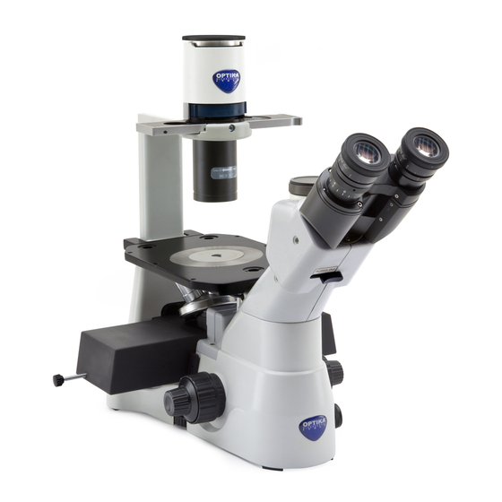
Page 5: Overview
Overview PHASE HOUSING CONTRAST SLIDER EYEPIECE TRINOCULAR VIEWING TUBE (FIXED) FILTER HOLDER CONDENSATOR ANTI-GLOW CAP DIOPTRIC ADJUSTMENT GLASS STAGE RING INSERT STAGE LIGHT PATH SELECTOR LEVER OBJECTIVE MICROSCOPE BODY FINE FOCUS KNOB TENSION COARSE ADJUSTMENT COLLAR FOCUS KNOB Page 5... -
Page 6: Unpacking
Unpacking The microscope is housed in a moulded Styrofoam container. Remove the tape from the edge of the container and lift the top half of the container. Take some care to avoid that the optical items (objectives and eyepieces) fall out and get damaged. Using both hands (one around the arm and one around the base), lift the microscope from the container and put it on a stable desk. - Page 7 Installing the objectives ② ① 1. Turning the coarse focusing knob till the nosepiece reaches its lowest position. ► For a safe transport, the nosepiece is placed in the lowest position and the ① ② tension adjustment collar is adjust- ed to the appropriate tension when the Fig.1 microscope leaves the factory.
- Page 8 Installing the stage insert 1. When using the glass stage, make sure that the insert is horizontal. 2. Install the stage insert in the stage opening. (Fig.6) Fig.6 Installing the eyepieces Insert both eyepieces into the tubes of the Fig.7 optical head.
- Page 9 Installing the fluorescence • When using the epifluorescence, you can mount the anti-glow cap on the bottom of the condenser, in order to increase the contrast of the image. (Fig.13) Fig.13 • Unscrew the protection cover on the left side of the microscope, with the provided allen wrench.
-
Page 10: Using The Microscope
Using the microscope INITIAL SETUP Turning on the LED ① Fig.18 Connect the power, turn on the main switch ①. (Fig.18) Position I: BF Position II: Epifluorescence Adjusting the brightness Turn the brightness adjustment knob ② to increase and decrease the brightness. (Fig.19) ②... - Page 11 VIEWING TUBE ① Dioptric adjustment Look into the right eyepiece with your right eye only, and focus on the specimen. Look into the left eyepiece with your left eye only. If the image is not sharp, use the dioptric adjustment ring ① to compen- sate.
- Page 12 ILLUMINATION UNIT Using color filters Selecting the appropriate color filters accord- ing your need. (Fig.24) You can stack a group of color filters in the fil- Fig.24 ter holder, if you ensure that they are level and that the whole thickness is less than 11mm. 70-80% Using the aperture diaphragm ①...
- Page 13 Centering the ring ► Usually this operation is not needed. If necessary, please proceed with the fol- lowing steps: Place a specimen on the stage and focus Take out the eyepiece from the tube with- out the dioptric adjustment, and replace it Fig.28 with the centering telescope (CT).
- Page 14 MICROPHOTOGRAPHY Installing the photography adapter 1. To activate the video port, pull the light path selector lever to “In” position. (Fig.31) 2. Loosen the locking bolt ① on the trinocu- lar viewing tube, and take out the dust cap ②. 3.
-
Page 15: Maintenance
Do not disassemble objectives or eyepieces in attempt to clean them. For the best results, use the OPTIKA cleaning kit (see catalogue). If you need to send the microscope to Optika for maintenance, please use the original packaging. Page 15... -
Page 16: Troubleshooting
Troubleshooting Review the information in the table below to troubleshoot operating problems. PROBLEM CAUSE SOLUTION I. Optical Section: The illumination is open, but the field The plug of the LED holder is Connect them of view is dark. not connected to the illumina- tion set The brightness is too low Adjust to a proper setting... - Page 17 One side of the image is out of focus. The nosepiece is not in the Turn the nosepiece to a click stop center of the light path The specimen is out of place Place the specimen flat on the stage. (tilted) The optical performance of the Use a cover glass of better quality...
-
Page 18: Equipment Disposal
Equipment disposal Art.13 Dlsg 25 july 2005 N°151. “According to directives 2002/95/EC, 2002/96/EC and 2003/108/EC relating to the reduction in the use of hazardous substances in electrical and electronic equipment and waste disposal.” The basket symbol on equipment or on its box indicates that the product at the end of its useful life should be collected separately from other waste. - Page 19 Serie IM MANUALE D’ISTRUZIONI Modello IM-3LD Versione: 3 Emesso il: 03, 05, 2019...
- Page 20 Indice Contenuti Avvertenza Simboli Informazioni sulla sicurezza Utilizzo previsto Elenco accessori e parti di ricambio Descrizione dello strumento Disimballagio Assemblaggio Istruzioni per l’uso Manutenzione Risoluzione problemi Smaltimento Pagina 20...
- Page 21 Avvertenza Questo microscopio è uno strumento scientifico di alta precisione, progettato per durare a lungo con una minima manutenzione; la realizzazione è secondo i migliori standard ottici e meccanici, per poter essere utilizzato quotidianamente. Vi ricordiamo che questo manuale contiene informazioni importanti per la sicurezza e per la manutenzione dello strumento, e deve quindi essere messo a disposizione di coloro che lo utilizzeranno.
- Page 22 Elenco accessori e parti di ricambio CAT. NO. DESCRIZIONE M-780 Oculare EWF10x/22mm. M-781 Oculare micrometrico EWF10x/22mm. M-005 Vetrino micrometrico per calibrazione software, 1mm/10um, 10mm/100um M-782 Obiettivo IOS LWD PLAN Acromatico 4x/0,10 (w.d. 22mm). M-782.1 Obiettivo IOS LWD PLAN Acromatico per contrasto di fase 4x/0.13 (w.d. 16.9mm). M-783N Obiettivo IOS LWD PLAN Acromatico per contrasto di fase 10x/0,25 (w.d.
- Page 23 Descrizione dello strumento ALLOGGIAMENTO SLIDER PER CONTRASTO DI FASE OCULARI TUBO DI USCITA TRINOCULARE PORTA-FILTRI CONDENSATORE TAPPO ANTIRIFLESSO ANELLO DI INSERTO REGOLAZIONE PORTAPREPARATI DIOTTRICA IN VETRO TAVOLINO SELEZIONATORE PERCORSO LUMINOSO OBIETTIVI MANOPOLA DI BASE DEL REGOLAZIONE MICROSCOPIO DELLA MESSA A FUOCO MANOPOLA DI MICROMETRICA...
- Page 24 Disimballagio Il microscopio è riposto in un imballo di polistirolo espanso. Rimuovere il nastro adesivo dal collo ed aprire la parte superiore dell’imballo. Fare attenzione a non far cadere le parti ottiche (obiettivi e oculari) nell’estrarre il microscopio dalla scatola per evitare che vengano danneggiati. Utilizzare entrambe le mani (una intorno allo stativo e una alla base), sfilare il microscopio dal contenitore e appoggiarlo su un piano stabile.
- Page 25 Installazione degli obiettivi ② 1. Ruotare la manopola di regolazione macro- ① metrica finché la torretta portaobiettivi si trova nella posizione più bassa. ► Per garantire la sicurezza durante il tra- sporto, prima della spedizione la torret- ① ta viene messa nella posizione più bas- sa e si sistema l’anello di regolazione Fig.1 ②...
- Page 26 Installazione dell’inserto in vetro 1. Assicurarsi che il piano portapreparati sia perfettamente orizzontale quando si usa il piano in vetro. 2. Inserire l’inserto in vetro nell’apertura del piano. (Fig.6) Fig.6 Installazione degli oculari Togliere il tappo ai tubi portaoculari, inserire gli oculari nei tubi.
- Page 27 Installazione fluorescenza • Quando si utilizza l’epifluorescenza, po- tete montare il tappo anti-riflesso sulla parte inferiore del condensatore, in modo da aumentare il contrasto dell’immagine. (Fig.13) Fig.13 • Svitare il coperchio di protezione alla sinis- tra dello stativo, con la chiave a brugola fornita.
- Page 28 Istruzioni per l’uso SETUP INIZIALE Accensione del LED Connettere l’alimentazione, accendere ① Fig.18 l’interruttore principale ①. (Fig.18) Posizione I: BF Posizione II: Epifluorescenza Regolazione della luminosità Ruotare l’apposita manopola per aumentare o diminuire la luminosità ②. (Fig.19) ② Regolazione della tensione Fig.19 ►...
- Page 29 OCULARI ① Compensazione diottrica Osservare e mettere a fuoco il preparato guardando con l’occhio destro attraverso l’oculare destro. Ora guardare attraverso l’oculare sini- stro con l’occhio sinistro. Se l’immagine non è nitida, agire sulla compensazione diottrica utilizzando l’apposito anello ①. (Fig.21) Fig.21 ►...
- Page 30 GRUPPO ILLUMINATORE Utilizzo filtri cromatici Scegliere i filtri cromatici a seconda delle proprie esigenze. (Fig.24) Nel portafiltri si possono ammucchiare una Fig.24 serie di filtri purché siano disposti piani e lo spessore totale sia inferiore a 11mm. Utilizzo del diaframma di apertura 70-80% ①...
- Page 31 ALLINEAMENTO DEI DIAFRAMMI ► Solitamente non è necessario effettuare questa operazione. Nel caso lo fosse, seguire procedura descritta seguito: Posizionare un preparato sul piano e metterlo a fuoco. Estrarre l’oculare tubo senza Fig.28 compensazione diottrica e sostituirlo con il telescopio di centratura (CT). (Fig.28) Verificare che l’anello di fase e l’obiettivo corrispondano e che entrambi siano fissi in posizione di blocco.
- Page 32 MICROFOTOGRAFIA Installazione dell’adattatore fotografico 1. Per attivare l’acquisizione video, tirare verso l’esterno la levetta di selezione del percorso luminoso. (Fig.31) 2. Svitare il bullone di bloccaggio ① sul tubo trinoculare e rimuovere il tappo antipolvere ②. 3. Installare l’adattatore foto nella porta Fig.31 trinoculare seguendo le istruzioni, quindi riavvitate il bullone di bloccaggio ①.
- Page 33 Non smontare gli obiettivi o gli oculari per cercare di pulirli. Per un migliore risultato, utilizzare il kit di pulizia OPTIKA (vedi catalogo). Se si necessita di spedire il microscopio al produttore per la manutenzione, si prega di utilizzare l’imballo originale.
- Page 34 Risoluzione problemi Consultare le informazioni riportate nella tabella sottostante per risolvere eventuali problemi operativi. PROBLEMA CAUSA SOLUZIONE I. I. Problemi ottici: 1. L’illuminatore è acceso, ma il cam- La spina dell’alloggiamento Collegare l’alloggiamento LED al gruppo po visivo è scuro LED non è...
- Page 35 6. Un lato dell’immagine non è a Il revolver non è al centro del Ruotare il revolver finché non si blocca con fuoco percorso luminoso un click Il preparato non si trova nella Posizionare il preparato orizzontalmente posizione corretta (es. inclinato) sul piano La qualità...
- Page 36 Smaltimento Ai sensi dell’articolo 13 del decreto legislativo 25 luglio 2005 n°151. “Attuazione delle direttive 2002/95/CE, 2002/96/CE e 2003/108/CE, relative alla riduzione dell’uso di sostanze pericolose nelle apparecchiature elettriche ed elettroniche, nonché allo smaltimento dei rifiuti”. Il simbolo del cassonetto riportato sulla apparecchiatura o sulla sua confezione indica che il prodotto alla fine della propria vita utile deve essere raccolto separatamente degli altri rifiuti.
- Page 37 Series IM MANUAL DE INSTRUCCIONES Modelo IM-3LD Version: Issued: 03, 05, 2019...
- Page 38 Cuadro de contenidos Advertencia Símbolos Información de seguridad Utilización Lista de accesorios y repuestos Vista general Desembalaje Montaje Instalación Mantenimiento Résolution des problèmes Eliminación de residuos Página 38...
- Page 39 Advertencia Este microscopio es un instrumento científico de precisión. Su utilización está pensada para una larga duración con un mínimo nivel de mantenimiento. Para su fabricación se han utilizado elementos ópticos y mecánicos de elevada calidad que lo convierten en el instrumento ideal para la utilización diaria en las aulas y el laboratorio. Informamos que esta guía contiene importantes informaciones sobre la seguridad y el mantenimiento del pro- ducto y por lo tanto debe ser accesible a todos aquellos que utilizan dicho instrumento.
- Page 40 Lista de accesorios y repuestos CAT. NO. DESCRIPCIÓN M-780 Ocular EWF10x/22mm. M-781 Ocular micrométrico EWF10x/22mm. M-005 Preparación micrométrica, 1mm/10um, 10mm/100um para la calibración del software M-782 Objetivo IOS PLAN LWD 4x/0.10 M-782.1 Objetivo IOS PLAN LWD PH 4x/0.13 M-783N Objetivo IOS PLAN LWD PH 10x/0.25 M-784N Objetivo IOS PLAN LWD PH 20x/0.40 M-785...
- Page 41 SOPORTE PARA Vista general CONTRASTE DE SOPORTE FASE OCULARES TUBO DE ENFOQUE TRINOCULAR SOPORTE PARA FILTRO CONDENSADOR TAPA ANTI BRILLOS ANILLO DE REGULACIÓN DIÓPTRICA DISCO DE VIDRIO PLATINA PALANCA DE SELECCIÓN DEL RECORRIDO OBJETIVOS LUMINOSO BASE DEL MANDO DE MICROSCOPIO REGULACIÓN DEL ENFOQUE MICROMÉTRICO...
- Page 42 Desembalaje El microscopio esta embalado dentro de una caja de porexpan. Quitar el precinto que hay alrededor de la caja y abrirla. Tenga cuidado al abrir la caja ya que algunos accesorios ópticos como objetivos y oculares podrían caerse o dañarse. Con las dos manos (una sujetando el brazo y la otra la base) extraer el microscopio de dentro la caja de porexpan y poner sobre la mesa, procurando que ésta sea fuerte y estable.
- Page 43 Instalación de los objetivos ② 1. Girar el mando de regulación macrométri- ① hasta que el revólver porta-objetivos se situé en su posición más baja. ► Para garantizar la seguridad durante el transporte, antes del envío, el revólver ① se coloca en la posición más baja y el ②...
- Page 44 Instalación del disco de vidrio 1. Asegurarse que la platina portapreparados esté perfectamente horizontal cuando se usa el soporte de vidrio. 2. Introducir el soporte de vidrio en el orificio Fig.6 de la platina. (Fig.6) Instalación de los oculares Introducir los oculares en los tubos. (Fig.7) Fig.7 Instalación del sistema condensador-iluminador y del LED...
- Page 45 Instalar la fluorescencia • Montar la tapa anti reflejos debajo del con- densador de luz para obtener mayor con- traste de la imagen cuando trabaje con epifluorescencia. (Fig.13) Fig.13 • Desatornillar con la llave allen que se suministra con el microscopio, la tapa de protección que hay en la parte izquierda del mismo.
- Page 46 Instalación CONFIGURACIÓN INICIAL Encender el LED Enchufar el microscopio a la corriente y ① Fig.18 encenderlo mediante el botón ①. Posición I: Campo claro Posición II: Epifluorescencia (Fig.18) Regulación de la luminosidad Girar el correspondiente mando ② para aumentar y para disminuir la luminosidad. (Fig.19) ②...
- Page 47 OCULARES ① Compensación dióptrica Observar y enfocar el preparado mirando con el ojo derecho a través del ocular derecho. A continuación, mirar a través del ocular izquierdo con el ojo izquierdo. Si la imagen no es nítida, regular la compensación dióptrica utilizando el correspondiente anillo ①.
- Page 48 SISTEMA DE ILUMINACIÓN Utilización de filtros cromáticos Elegir los filtros cromáticos en función de las propias exigencias. (Fig.24) En el portafiltros se pueden colocar varios Fig.24 filtros con tal de que estén planos y el espesor total sea inferior a 11mm. Utilización del diafragma de apertura 70-80% ①...
- Page 49 Centrado del círculo luminoso ► Normalmente no es necesario realizar esta operación. Si fuera necesario, seguir el proceso que se describe a continuación: Situar un preparado en la platina y enfocarlo. Fig.28 Extraer el ocular del tubo sin compensación dióptrica y sustituirlo por el telescopio de centrado (CT).
- Page 50 MICROFOTOGRAFÍA Instalación del adaptador para foto 1. Para activar la adquisición de video, tirar la palanca de selección del recorrido luminoso hacia el exterior. (Fig.31) 2. Destornillar el tornillo de bloqueo ① del tubo trinocular y extraer el tapón antipolvo ②.
- Page 51 No desmontar los objetivos o los oculares para intentar limpiarlos. Para obtener mejores resultados, utilice el kit de limpieza OPTIKA (véase el catálogo). Si fuera necesario, enviar el microscopio a la empresa Optika para su mantenimiento se ruega utilizar el embalaje original.
- Page 52 Résolution des problèmes Revisar la información en la tabla a continuación para solucionar problemas de funcionamiento. PROBLEMA CAUSA SOLUCION I. Section Optique: El iluminador está El enchufe del LED soporte no Conectar el LED soporte al sistema de encendido, pero el campo está...
- Page 53 Un lado de la imagen El revólver no está en el centro Girar el revólver hasta que no se bloquee no está enfocado del recorrido luminoso con un click El preparado no está en la po- Situar el preparado horizontal al plano sición correcta (ej.
- Page 54 Eliminación de residuos En conformidad con el Art. 13 del D.L. de 25 julio 2005 n°151. Actuación de las Directivas 2002/95/CE, 2002/96/ CE y 2003/108/CE, relativas a la reducción del uso de sustancias peligrosas en la instrumentación eléctrica y electrónica y a la eliminación de residuos. El símbolo del contenedor que se muestra en la instrumentación o en su embalaje indica que el producto cuando alcanzará...
- Page 55 IM Series MANUEL D’UTILISATION Modèle IM-3LD Version: 03, 05, 2019...
- Page 56 Contenu Avertissement Symboles Précautions Emploi prévu Liste des accessoires et pièces détachées Description Déballage Assemblage Opération Maintenance Réparation et entretien Résolution des problèmes Ramassage Page 56...
-
Page 57: Symboles
Avertissement Le présent microscope est un appareil scientifique de précision créé pour offrir une durrée de vie de plusieurs années avec un niveau d’entretien mininum. Les meilleurs composants optiques et mécaniques ont été utilisés pour sa conception ce qui fond de lui un appareil idéal pour une utilisation journalière. Ce guide contient des informations importantes sur la sécurité... -
Page 58: Liste Des Accessoires Et Pièces Détachées
Liste des accessoires et pièces détachées CAT. NO. DESCRIPTION M-780 Oculaire EWF10x/22mm. M-781 Oculaire micrométrique EWF10x/22mm. M-005 Lame micrométrique pour étalonnage logiciel, 1mm/10um, 10mm/100um M-782 Objectif IOS PLAN LWD 4x/0.10 M-782.1 Objectif IOS PLAN LWD PH 4x/0.13 M-783N Objectif IOS PLAN LWD PH 10x/0.25 M-784N Objectif IOS PLAN LWD PH 20x/0.40 M-785... -
Page 59: Description
Description ILLUMINATEUR DISPOSITIF CONTRASTE DE PHASE OCULAIRES TUBE D’OBSERVATION TRINOCULAIRE PORTE-FILTRE CONDENSEUR PROTECTION ANTI-REFLETS ANNEAU D’AJUSTEMENT DIOPTRIQUE PLATINE EN VERRE PLATINE LEVIER DE SÉLECTION DE LUMIÈRE OBJECTIF STATIF DU MISE AU POINT MICROSCOPE MICROMETRIQUE MISE AU POINT MACROMETRIQUE RÉGLAGE TENSION Page 59... -
Page 60: Déballage
Déballage Le microscope est logé dans un récipient en polystyrène moulé. Retirez la bande du bord du récipient et soulevez la moitié supérieure du récipient. Prenez soin d’éviter que les objets optiques (objectifs et oculaires) tombent et se détériorent. En utilisant les deux mains (une autour du bras et une autour de la base), soulevez le microscope du récipient et mettez-le sur un bureau stable. - Page 61 Installation des objectifs ② ① 1. Tournant le bouton de la mise au point jusqu’à la plus basse position du revolver. ► Pour un transport sûr, le revolver est placé dans la position la plus basse et ① le bouton de commande de la tension ②...
- Page 62 Installation de la platine d’insertion 1. En utilisant la plate-forme en verre s’assu- rer que l’insert est horizontale. 2. Installer la plate-forme dans l’ouverture de la platine. (Fig.6) Fig.6 Installation des oculaires Enlever le bouchon des tubes oculaire, insérer les oculaires dans les tubes. (Fig.7) Fig.7 Installation du condenseur L’unité...
- Page 63 Installer la fluorescence • Lorsque vous utilisez l’épifluorescence, vous pouvez monter le capuchon anti-re- flet sur le fond du condenseur, afin d’aug- menter le contraste de l’image. (Fig.13) Fig.13 • Dévissez le couvercle de protection sur le côté gauche du microscope, avec la clé allen fournie.
-
Page 64: Opération
Opération INSTALLATION INITIALE Mise sous tension de la LED Branchez l’appareil, mettez l’interrupteur ① Fig.18 principal ① sous tension. (Fig.18) Position I: BF Position II: Epifluorescence Réglage éclairage Tourner le bouton de commande de l’éclairage ② pour augmenter et abaisser l’éclairage. (Fig.19) ②... - Page 65 TUBE D’OBSERVATION ① Ajustement dioptrique Observer à travers l’oculaire juste avec votre oeil droit et focaliser l’échantillon. Observer à travers l’oculaire gauche avec seulement votre oeil gauche. Si l’image n’est pas nette, utiliser l’anneau de réglage dioptrique ① pour compenser. (Fig.21) ►...
- Page 66 UNITE D’ILLUMINATION Usage des filtres en couleur Le choix de la couleur appropriée selon votre besoin. (Fig.24). Vous pouvez empiler un groupe de filtres en couleur dans le porte- filtres, s’assurant qu’ils sont de niveau et Fig.24 d’épaisseur entièrement inférieurs à 11 milli- mètres.
- Page 67 Centrage de l’anneau ► D’habitude cette opération n’est pas nécessaire. nécéssité, éffectuer les opérations suivantes: Placer un échantillon sur la platine et focaliser. Enlever l’oculaire du tube sans le réglage dioptrique et le remplacer par le télescope Fig.28 de centrage (CT). (Fig.28) Vérifier que l’anneau de phase et l’objectif correspondent et que tous les deux sont fermement mis sur l’...
- Page 68 MICROPHOTOGRAPHIE Installation de l’adaptateur de photographie 1. Pour activer la porte-vidéo, retirer le levier de sélection du parcours lumineux en position ‘IN’. (Fig.31) 2. Desserrer la butée de verrouillage ① sur le tube d’observation trinoculaire et enle- ver le bouchon antipoussières ②. 3.
-
Page 69: Réparation Et Entretien
• Les empreintes digitales peuvent endommager les parties optiques. Pour les meilleurs résultats, utiliser le kit de nettoyage OPTIKA (voir le catalogue). Conserver l’emballage d’origine dans le cas où il serait nécessaire de retourner le microscope au fournisseur pour un entretien ou une réparation. -
Page 70: Résolution Des Problèmes
Résolution des problèmes Passer en revue les informations dans le tableau ci-dessous pour résoudre les problèmes opérationnels. SOLUTION PROBLEME RAISON I. Section Optique: L’illumination est ouverte, mais le La prise de courant de la Les Brancher champ de vision est sombre. douille n’est pas branchée au jeu d’illumination L’éclairage est très faible... - Page 71 6. Un côté de l’image est flou. Le revolver n’est au centre du Tourner le revolver à un arrêt de parcours lumineux claquement L’échantillon est déplacé Place l’échantillon plat sur la platine (incliné) La performance optique Utiliser un verre de couverture de meilleure du verre de couverture de qualité...
-
Page 72: Ramassage
Ramassage Conformément à l’Article 13 du D.L du 25 Juillet 2005 nº151 Action des Directives 2002/95/CE, 2002/96/CE et 2003/108/CE, relatives à la réduction de l’utilisation de substances dangereuses dans l’appareil électrique et électronique et à l’élimination des résidus. Le Symbole du conteneur qui figure sur l’appareil électrique ou sur son emballage indique que le produit devra être, à... - Page 73 IM Series BEDIENUNGSANLEITUNG Model IM-3LD Version: Datum: 05, 03, 2019...
- Page 74 Inhalt Warnung Zeichen Sicherheitshinweise Verwendung Liste der Zubehör und Ersatzteile Beschreibung Öffnung der Verpackung Zusammenbau Bedienungsanleitung Wartung Störungssuche Wiederverwertung Pagina 74...
- Page 75 Warnung Dieses Mikroskop ist ein wissenschaftliches Präzisionsgerät, es wurde entwickelt für eine jahrelange Verwen- dung bei einer minimalen Wartung. Dieses Gerät wurde nach den höchsten optischen und mechanischen Standards und zum täglichen Gebrauch hergestellt. Diese Bedienungsanleitung enthält wichtige Informationen zur korrekten und sicheren Benutzung des Geräts. Diese Anleitung soll allen Benutzern zur Verfügung stehen. Wir lehnen jede Verantwortung für eine fehlerhafte, in dieser Bedienungsanleitung nicht gezeigten Verwen- dung Ihrer Produkte ab.
- Page 76 Liste der Zubehör und Ersatzteile CAT. NO. BESCHREIBUNG M-780 Okular EWF10x/22mm. M-781 Mikrometrisches Okular EWF10x/22mm. M-005 26x76 mm micrometric slide. Range 1 mm, div. 0,01 mm. M-782 Objektiv IOS PLAN LWD 4x/0.10 M-782.1 Objektiv IOS PLAN LWD PH 4x/0.13 M-783N Objektiv IOS PLAN LWD PH 10x/0.25 M-784N Objektiv IOS PLAN LWD PH 20x/0.40...
- Page 77 Beschreibung GEHÄUSE SLIDER FÜR PHASENKONTRAST OKULARE TRINOKULA- RAUSGANGSTUBUS (FIXED) FILTERTRÄGER FÜR FARBFILTER KONDENSOR ANTIGLÜH-KAPPE DIOPTRIENVERSTEL- LUNGSRING GLASSTUFEN EINFÜGEN TISCH LICHTWEGAUSWAHL OBJEKTIVE MIKROSKOPKÖRPER FEINTRIEBKNOPF SPANNUNGSEINSTELLUNG GROBTRIEBKNOPF Pagina 77...
- Page 78 Öffnung der Verpackung Das Mikroskop ist in einem geformten Schaumpolystyrol Verpackung verpackt. Entfernen Sie das Klebeband von der Verpackung und ziehen Sie die obere Hälfte der Verpackung hoch. Beachten Sie bitte, die optischen Be- standteile (Objektive und Okulare) nicht fallen zu lassen oder nicht zu beschädigen. Ziehen Sie das Mikroskop aus der Verpackung mit beiden Händen (eine um den Arm und eine um die Basis) heraus und legen Sie es auf eine stabile Oberfläche.
- Page 79 Installation der Objektive ② ① 1. Drehen Sie den Grobtriebknopf bis der Revolver sich in die tiefste Position befin- det. ► Aus Sicherheitsgründen wird der Re- volver vor dem Versand in die tiefste ① Position gesetzt und der Spannungs- ② ring wird zur richtigen Spannung Fig.1...
- Page 80 Installation des Glaseinsatzes 1. Prüfen Sie, die Einlage perfekt horizontal ist, als der Glaseinsatz verwendet wird. 2. Setzen Sie den Glaseinsatz in die Tischöffnung ein. (Fig.6) Fig.6 Installation der Okulare Nehmen Sie den Verschluss aus den Okulartuben heraus, etzen Sie die Okulare in den Tuben ein.
- Page 81 Montage der Fluoreszenz • Wenn Sie de Epifluoreszenz verwenden, können Sie die Anti-Schimmel Kappe an dem Boden des Kondensors montieren, um den Kontrast des Bildes zu erhöhen (Fig.13) Fig.13 • Unscrew the protection cover on the left side of the microscope, with the provided allen wrench.
- Page 82 Bedienungsanleitung STANDARDEINRICHTUNG Einschalten der LED Schliessen Sie das Gerät an und schalten Sie ① Fig.18 den Hauptschalter ein ①. (Fig.18) Position I: BF Position II: Epifluoreszenz Helligkeitseinstellung Drehen Sie den dafür vorgesehenen Knopf, um die Helligkeit zu erhöhen oder zu ②...
- Page 83 OKULARE ① Dioptrienverstellung Stellen Sie das Präparat scharf, als Sie mit der rechten Auge durch das rechte Okular betrachten. Dann betrachten Sie es mit dem linken Auge durch das linke Okular. Falls das Bild nicht scharf ist, ändern Sie die Diop- trienverstellung mit Hilfe des Ringes ①.
- Page 84 LEUCHTE GRUPPE Verwendung der Farbfilter Wählen Sie die Farbfilter nach Bedarf. (Fig.24) Es ist möglich, eine Filterserie im Filterträger zu schichten, vorausgesetzt dass sie eben Fig.24 sind und die Dicke insgesamt unter 11 mm ist. Verwendung der Aperturblende 70-80% ① Bei Hellfeldbetrachtungen steuert die Apertur- blende die numerische Apertur der Leuchte.
- Page 85 Zentrierung des Lichtrings ► Normalerweise ist diese Operation nicht nötig. Falls nötig, folgen Sie das unten beschriebene Verfahren: Positionieren Sie ein Präparat auf den Tisch und fokussieren Sie es. Entfernen Sie das Okular aus dem Tubus Fig.28 ohne Dioptrienverstellung und ersetzen Sie es mit dem Zentriererungsteleskop (ZT).
- Page 86 MIKROFOTOGRAFIE Installation des Foto-Adapters 1. Um die Videoaufnahme zu aktivieren, zie- hen Sie den Lichtweg-Auswahlhebel auf der Position “IN”. (Fig.31) 2. Schrauben Sie den Blockierbolzen ① auf dem Trinokulartubus auf und entfernen Sie die Staubkappe ②. 3. Installieren Sie den Foto-Adapter in den Fig.31 trinokularen Ausgang gemäß...
- Page 87 • Die Objektive oder die Okulare sollen bei der Reinigung nicht abgenommen werden. Für gute Ergebnisse verwenden Sie das OPTIKA Reinigungskit (siehe Katalog). Falls das Mikroskop zurück an uns für Wartung geschickt werden muss, verwenden Sie bitte die ursprüngliche Verpackung.
- Page 88 Störungssuche PROBLEM URSACHE LÖSUNG I. Optische Sektion: 1. Die Beleuchtung ist offen Der Stecker des Lampenträ- Verbinden Sie den Stecker aber das Betrachtungsfeld ist gers ist zum Beleuchtungs- dunkel atz nicht verbunden Helligkeit zu niedrig Helligkeit einstellen Zu vielen Filtern Filter abnehmen 2.
- Page 89 6. Eine Seite des Bildes ist Revolver nicht in der Mitte Drehen den Revolver bis er klickt nicht scharf des Lichtwegs Der Objekt ist in einer fal- Legen den Objekt falch auf dem Tisch. schen Position Die optische Leistung des Objektträgerglas wechseln Objektträgerglas ist schlecht II.
- Page 90 Wiederverwertung Gemäß dem Artikel 13 vom Dekret Nr. 151 vom 25.07.2005 “Umsetzung der Richtlinien 2002/95/EG, 2002/96/EG und 2003/108/EG in Bezug auf die Verwendung gefährlicher Stoffe in elektrischen und elektronischen Geräten sowie die Abfallentsorgung” Das Symbol vom Müllcontainer erscheint auf dem Gerät oder der Verpackung und weist darauf hin, dass das Produkt Ende des Lebens separat von anderen Abfällen entsorgt werden muss.
- Page 91 Série IM MANUAL DE INSTRUÇÕES Modelo IM-3LD Versão: Emitido: 03, 05, 2019...
- Page 92 Tabela de Conteúdos Advertência Símbolos Informações sobre a segurança Utilização prevista Conteúdo da embalagem Lista de acessórios e peças de substituição Visão geral Desembalando Procedimento de instalação Instruções para o uso Manutenção Resolução de problemas Eliminação Página 92...
- Page 93 Advertência Este microscópio é um instrumento científico de alta precisão, projetado para durar um longo tempo com manutenção mínima; a sua realização respeita os melhores padrões óticos e mecânicos, para que possa ser utilizado diariamente. Recordamos que este manual contém informações importantes para a segurança e a manutenção do instrumento, portanto deve ser colocado à...
- Page 94 Lista de acessórios e peças de substituição CAT. NO. DESCRIPTION M-780 Ocular EWF10x/22mm. M-781 Ocular micrométrico EWF10x/22mm. M-005 Slide micrométrico 26x76 mm. Gama de 1 mm, div. 0,01 mm. M-782 Objetiva IOS LWD PLAN Acromática 4x/0.10 (w.d. 22mm). M-782.1 Objetiva IOS LWD PLAN Acromática de Contraste de Fases 4x/0.13 (w.d. 16.9mm). M-783N Objetiva IOS LWD PLAN Acromática de Contraste de Fases 10x/0,25 (w.d.
- Page 95 COMPARTIMENTO Visão geral CONTROLE DE FASE SLIDER OCULARES TRINOCULAR VIEWING TUBE (FIXED) SUPORTE DO FILTRO CONDENSADOR FILTRO ANTI-BRILLOS ANEL DE INSERÇÃO AJUSTE DE PLATINA DIOPTRICO DE VIDRIO PLATINA SELECIONADOR DO NIVEL TRAJETÓRIA DA OBJETIVAS BASE DE BOTAO DE AJUSTE MICROSCÓPIO MACROMÉTRICO ARO DE BOTAO DE AJUSTE...
- Page 96 Desembalando O microscópio é alojado em um recipiente de isopor moldado. Remova a fita da borda do recipiente e levante a metade superior do recipiente. Tome algum cuidado para evitar que os itens ópticos (objetivos e oculares) cair e ficar danificado. Usando ambas as mãos (uma ao redor do braço e outra ao redor da base), levante o micros- cópio do recipiente e coloque-o em uma mesa estável.
- Page 97 Instalação das objetivas ② 1. Rodar manípulo regulação ① macrométrica até que a torre de objetivas esteja na posição mais baixa. Para garantir a segurança durante o ► transporte, antes da expedição a torre é ① colocada na posição mais baixa e o anel ②...
- Page 98 Instalação do elemento de vidro 1. Ao usar el elemento de vidro, certifique-se de que a inserção esteja na horizontal. 2. Inserir o elemento de vidro na abertura da placa. (Fig.6) Fig.6 Instalação das oculares Insira as duas oculares nos dos tubos porta- oculares.
- Page 99 Instalando a fluorescência • Ao usar a epifluorescência, você pode montar a tampa anti-brilho na parte infe- rior do condensador, a fim de aumentar o contraste da imagem. (Fig.13) Fig.13 • Desatornillar con la llave allen que se su- ministra con el microscopio, la tapa de protección que hay en la parte izquierda del mismo.
- Page 100 Instruções para o uso CONFIGURAÇÃO INICIAL Acendimento da iluminação ① Fig.18 Conectar a alimentação e acender o interruptor ①. (Fig.18) Regulação da luminosidade Rodar o manípulo específico ② para aumentar ou diminuir a luminosidade. (Fig.19) Regulação da tensão ② Fig.19 ►...
- Page 101 OCULARES ① Compensação dióptrica Observar e focalizar o preparado olhando com o olho direito através da ocular di- reita. Então, olhar através da ocular esquerda com o olho esquerdo. Se a imagem não for nítida, regular a compensação dióptri- ca utilizando o anel específico ①. (Fig.21) ►...
- Page 102 GRUPO ILUMINADOR Utilização de filtros cromáticos Escolher os filtros cromáticos de acordo com as próprias exigências. (Fig.24) No porta-filtros é possível acumular uma série Fig.24 de filtros desde que dispostos de forma plana e que a espessura total seja inferior a 11 mm. 70-80% Utilização do diafragma de abertura ①...
- Page 103 Centrando o anel de fase ► Geralmente não é necessário realizar esta operação. Se for necessária, seguir o procedimento descrito a seguir: Posicionar um preparado sobre a placa e focalizá-lo. Extrair a ocular do tubo sem compensação dióptrica e substituí-la pelo telescópio de Fig.28 centragem (CT).
- Page 104 MICROFOTOGRAFIA Instalação do adaptador foto 1. To activate the video port, pull the light path selector lever to “In” position. (Fig.31) 2. Desapertar o parafuso de bloqueio ① do tubo trinocular e remover a tampa para pó ②. 3. Instalar o adaptador foto na porta trinocu- lar seguindo as instruções e, então, aper- Fig.31 tar novamente o parafuso de bloqueio ①.
- Page 105 Não desmontar as objetivas ou os oculares para tentar limpá-los. Para um melhor resultado utilizar o kit de limpeza OPTIKA (ver catálogo). Se for necessário enviar o microscópio ao fabricante para a sua manutenção, pede-se que seja utilizada a emba- lagem original.
- Page 106 Resolução de problemas Reveja a informação na tabela abaixo para tentar solucionar problemas de operação. PROBLEMA CAUSE SOLUTION I. Secção Óptica: A iluminação está aberta, mas o O plugue do suporte da lâm- Conecte-os pada não está conectado ao campo de visualização está escu- grupo de iluminação O brilho é...
- Page 107 6. Um lado da imagem está for a A peça nasal não está no cen- Rode a peça nasal para um bloqueio com de foco tro do percurso da luz clique A amostra está fora do lugar Coloque a amostra plana sobre a platina. (saltou) O desempenho óptico do vidro Use um vidro de cobertura de melhor...
- Page 108 Eliminação Em conformidade com o artigo 13 do decreto legislativo de 25 de julho 2005 n°151. "Atuação das diretivas 2002/95/CE, 2002/96/CE e 2003/108/CE, relativas à redução do uso de substâncias perigosas nos aparelhos elétricos e eletrónicos, assim como a eliminação dos resíduos. O símbolo do caixote presente no aparelho ou na sua embalagem indica que o produto no final da sua vida útil deve ser eliminado separadamente dos outros produtos.
- Page 110 OPTIKA S.r.l. ® Via Rigla, 30 - 24010 Ponteranica (BG) - ITALY Tel.: +39 035.571.392 info@optikamicroscopes.com - www.optikamicroscopes.com OPTIKA Spain spain@optikamicroscopes.com OPTIKA USA usa@optikamicroscopes.com OPTIKA China china@optikamicroscopes.com OPTIKA India india@optikamicroscopes.com OPTIKA Central America camerica@optikamicroscopes.com...
Need help?
Do you have a question about the IM Series and is the answer not in the manual?
Questions and answers