Table of Contents
Advertisement
Quick Links
Advertisement
Table of Contents

Related Manuals for Optika IM-2


Summary of Contents for Optika IM-2
- Page 1 IM Series INSTRUCTION MANUAL Model IM-2 IM-2ERGO Version: Issued: 30, 05, 2016...
-
Page 2: Table Of Contents
Table of Contents Warning Symbols and conventions Safety Information Intended use List of accessories and spare parts Overview Unpacking Assembling Using the microscope Maintenance Troubleshooting Equipment disposal Page 2... -
Page 3: Symbols And Conventions
Warning This microscope is a scientific precision instrument designed to last for many years with a minimum of mainte- nance. It is built to high optical and mechanical standards and to withstand daily use. We remind you that this manual contains important information on safety and maintenance, and that it must therefore be made acces- sible to the instrument users. -
Page 4: List Of Accessories And Spare Parts
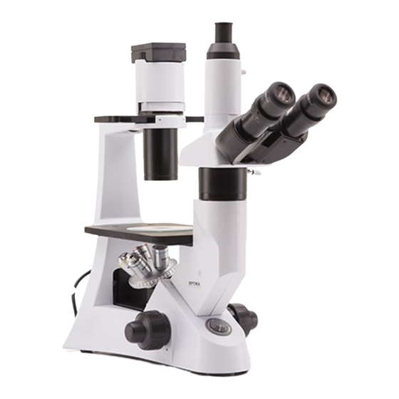
Phase ring 40x (to use with M-774). M-778 C-mount adapter for 1/3”,1/2” and 2/3” sensor. M-036 Dust cover type 7. M-795 Fluorescence attachment, HBO100W, B and G filtersets (only for IM-2). M-792.1 Mechanical stage for IM-2 series. M-793.1 Holder for Petri diameter 38mm (M-793.2 needed). M-793.2 Holder for Terasaki and Petri diameter 65mm. - Page 5 Overview HOUSING TRINOCULAR VIEWING TUBE (FIXED) EYEPIECE FILTER HOLDER PHASE CONTRAST SLIDER CONDENSER DIOPTRIC ADJUSTMENT RING GLASS STAGE INSERT STAGE OBJECTIVE MICROSCOPE BODY LIGHT ADJUSTEMENT MAIN SWITCH TENSION FINE FOCUS KNOB ADJUSTMENT COARSE COLLAR FOCUS KNOB Page 5...
-
Page 6: Unpacking
Unpacking The microscope is housed in a moulded Styrofoam container. Remove the tape from the edge of the container and lift the top half of the container. Take some care to avoid that the optical items (objectives and eyepieces) fall out and get damaged. Using both hands (one around the arm and one around the base), lift the microscope from the container and put it on a stable desk. -
Page 7: Installing The Objectives
Installing the optical head 1. Take out the dust cap and fix the optical ① head using the screw . (Fig.1) 2. Insert the trinocular tube into the exit above ② the head, and fix it using the screw (Fig.2) ①... - Page 8 Installing the stage extension and the mechanical stage (OPTIONAL) The stage extension can be installed on either side of the stage to enlarge the working sur- face. The mechanical stage must be installed on the side opposite the extension. For right-handed operators, the mechanical stage is normally installed on the right side.
-
Page 9: Installing The Condenser
Installing the condenser illumination unit and the LED housing 1. Insert the condenser illumination unit into the bracket. (Fig.10) 2. Turn the condenser illumination unit Fig.10 clockwise about 90°, with the “AS” mark of filter holder facing forwards. Screw the 2 fixing mut with the supplied allen wrench. -
Page 10: Connecting The Power Cord
Connecting the power cord Turn the main switch ① to “O”(off) before connecting the power cord. (Fig.15) Insert the cable into the power socket of the microscope. (Fig.16) Plug the power cord into the mains sock- et. Check for a safe connection. ①... -
Page 11: Using The Microscope
When switching objectives, take care not to touch the adaptor plates with the objectives, as their weight may M-793.6 damage the front lens. Holder for Utermöhl-Chamber (M-793.3 needed). M-793.8 Load-bearing side extension for IM-2 series M-792.1 Mechanical stage for IM-2 series. Page 11... - Page 12 VIEWING TUBE ① Dioptric adjustment Look into the right eyepiece with your right eye only, and focus on the specimen. Look into the left eyepiece with your left eye only. If the image is not sharp, use the dioptric adjustment ring ① to compen- sate.
-
Page 13: Illumination Unit
ILLUMINATION UNIT Using color filters Selecting the appropriate color filters accord- ing your need. (Fig.22) You can stack a group of color filters in the fil- Fig.22 ter holder, if you ensure that they are level and that the whole thickness is less than 11mm. 70-80% Using the aperture diaphragm ①... - Page 14 MICROPHOTOGRAPHY Installing the photography adapter 1. To activate the video port, pull out light path selector lever. (Fig.26) 2. Install the photography adapter into the trinocular port according to its instructions. Fig.26 (Fig.27) 3. Attach the camera ring (if any) to the adapter.
-
Page 15: Maintenance
Do not disassemble objectives or eyepieces in attempt to clean them. For the best results, use the OPTIKA cleaning kit (see catalogue). If you need to send the microscope to Optika for maintenance, please use the original packaging. Page 15... -
Page 16: Troubleshooting
Troubleshooting Review the information in the table below to troubleshoot operating problems. PROBLEM CAUSE SOLUTION I. Optical Section: The illumination is open, but the field The plug of the LED holder is Connect them of view is dark. not connected to the illumina- tion set The brightness is too low Adjust to a proper setting... - Page 17 One side of the image is out of focus. The nosepiece is not in the Turn the nosepiece to a click stop center of the light path The specimen is out of place Place the specimen flat on the stage. (tilted) The optical performance of the Use a cover glass of better quality...
-
Page 18: Equipment Disposal
Equipment disposal Art.13 Dlsg 25 july 2005 N°151. “According to directives 2002/95/EC, 2002/96/EC and 2003/108/EC relating to the reduction in the use of hazardous substances in electrical and electronic equipment and waste disposal.” The basket symbol on equipment or on its box indicates that the product at the end of its useful life should be collected separately from other waste. - Page 20 OPTIKA S.r.l. ® Via Rigla, 30 - 24010 Ponteranica (BG) - ITALIA Tel.: +39 035.571.392 - Fax: +39 035.571.435 info@optikamicroscopes.com - www.optikamicroscopes.com OPTIKA Spain ® spain@optikamicroscopes.com OPTIKA USA ® usa@optikamicroscopes.com OPTIKA China ® china@optikamicroscopes.com OPTIKA Hungary ® hungary@optikamicroscopes.com...
Need help?
Do you have a question about the IM-2 and is the answer not in the manual?
Questions and answers