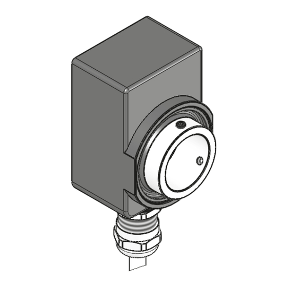
Summary of Contents for Siko GS04
- Page 1 GS04 Hohlwellensensor Deutsch Originalmontageanleitung Seite 2 Hollow shaft sensor English Translation of the Original Installation Instructions page 10 154/15...
-
Page 2: Table Of Contents
2.2 Kennzeichnung von Gefahren und Hinweisen 2.3 Zielgruppe 2.4 Grundlegende Sicherheitshinweise 3 Identifikation 4 Installation 4.1 Mechanische Montage 4.2 Elektrische Installation 5 Inbetriebnahme 6 Transport, Lagerung, Wartung und Entsorgung 7 Technische Daten GS04 · Datum 15.04.2015 · Art. Nr. 86318 · Änd. Stand 154/15... -
Page 3: Dokumentation
Todesfolge, Sachschäden oder ungeplanten Gerätereaktionen führen können, sofern Sie die gegebenen Anweisungen missachten. Gefährdungen die zu schweren Körperverletzungen, Sachschäden oder WARNUNG ungeplanten Gerätereaktionen führen können, sofern Sie die gegebenen Anweisungen missachten. GS04 · Datum 15.04.2015 · Art. Nr. 86318 · Änd. Stand 154/15... -
Page 4: Zielgruppe
Automatisierungstechnik vertraut sind; • als Inbetriebnahme- und Monatagepersonal berechtigt sind, Strom- kreise und Geräte/Systeme gemäß den Standards der Sicherheitstech- nik in Betrieb zu nehmen, zu erden und zu kennzeichnen. GS04 · Datum 15.04.2015 · Art. Nr. 86318 · Änd. Stand 154/15... -
Page 5: Grundlegende Sicherheitshinweise
Belastung sowie Erwärmung und langfristig zur Zerstörung des Sensors. ` Sorgen Sie für einen geringen Wellen- und Winkelversatz zwischen Welle und Aufnahmebohrung durch geeignete Fertigungsmaßnahmen Abb. 1 Tab. (siehe GS04 · Datum 15.04.2015 · Art. Nr. 86318 · Änd. Stand 154/15... - Page 6 Bohrung einführen (verspannungsfreie Montage). Ein Lang- loch für die Drehmomentstütze wird empfohlen. 2. Gewindestifte M3 mit maximal 0.2 Nm anziehen. Abb. 2: Montage Abb. 3: Anzugsmoment Gewindestift GS04 · Datum 15.04.2015 · Art. Nr. 86318 · Änd. Stand 154/15...
-
Page 7: Elektrische Installation
Cos/ Elektrischer Anschluss E15 + E17 Dieser Sensor ist vorbereitet zum Anschluss an eine SIKO-Positionsan- ACHTUNG zeige. Der Sensoranschluss darf nicht verändert (z. B. durch Kabelverlän- gerungen) werden. GS04 · Datum 15.04.2015 · Art. Nr. 86318 · Änd. Stand 154/15... -
Page 8: Inbetriebnahme
Die elektronischen Bauteile des Sensors enthalten umweltschädigende Stoffe und sind zugleich Wertstoffträger. Der Sensor muss deshalb nach seiner endgültigen Stilllegung einem Recycling zugeführt werden. Die Umweltrichtlinien des jeweiligen Landes müssen hierzu beachtet werden. GS04 · Datum 15.04.2015 · Art. Nr. 86318 · Änd. Stand 154/15... -
Page 9: Technische Daten
Ergänzung Umgebungstemperatur 0 ... 60 °C Lagertemperatur -20 ... 70 °C relative Luftfeuchtigkeit Betauung nicht zulässig EN 61000-6-2 Störfestigkeit / Immission EN 61000-6-4 Störaussendung / Emission Schutzart IP65 EN 60529 GS04 · Datum 15.04.2015 · Art. Nr. 86318 · Änd. Stand 154/15... - Page 10 2.3 Target group 2.4 Basic safety information 3 Identification 4 Installation 4.1 Mechanical mounting 4.2 Electrical Installation 5 Commissioning 6 Transport, Storage, Maintenance and Disposal 7 Technical data GS04 · Date 15.04.2015 · Art. No. 86318 · Mod. status 154/15...
-
Page 11: Documentation
Danger that may cause minor injury, property damage or unplanned device CAUTION reactions if you disregard the instructions given. GS04 · Date 15.04.2015 · Art. No. 86318 · Mod. status 154/15... -
Page 12: Target Group
Bruising, rubbing, abrasing, seizing of extremities or clothes by touching during operation any rotating parts as for example clamping ring, torque support or hollow shaft. ` Prevent people from access by installing protective facilities. GS04 · Date 15.04.2015 · Art. No. 86318 · Mod. status 154/15... -
Page 13: Identification
` When mounting pay attention to the IP type of protection (see chap- ter 7). ` Do not open the sensor yourself. ` Avoid impact on the device. ` Do not modify the device in any way. GS04 · Date 15.04.2015 · Art. No. 86318 · Mod. status 154/15... - Page 14 (nondistorted mounting). A long hole for the torque support is recommended. 2. Tighten grub screws M3 with max. 0.2 Nm. Fig. 2: Mounting Fig. 3: Fastening torque for grub screw GS04 · Date 15.04.2015 · Art. No. 86318 · Mod. status 154/15...
-
Page 15: Electrical Installation
Electrical connection E16 This sensor have been prepared for connection to SIKO electronic display. NOTICE No modification of the sensor connection (e. g. cable modification) is per- mitted. GS04 · Date 15.04.2015 · Art. No. 86318 · Mod. status 154/15... -
Page 16: Commissioning
Therefore, the sensor must be recycled after it has been taken out of ope- ration ultimately. Observe the environment protection guidelines of your country. GS04 · Date 15.04.2015 · Art. No. 86318 · Mod. status 154/15... -
Page 17: Technical Data
0 ... 60 °C Storage temperature -20 ... 70 °C Relative humidity condensation inadmissible EN 61000-6-2 interference resistance / immission EN 61000-6-4 emitted interference / emission Protection category IP65 EN 60529 GS04 · Date 15.04.2015 · Art. No. 86318 · Mod. status 154/15... - Page 18 GS04...
- Page 19 GS04...
- Page 20 SIKO GmbH Weihermattenweg 2 79256 Buchenbach Telefon/Phone + 49 7661 394-0 Telefax/Fax + 49 7661 394-388 E-Mail info@siko.de Internet www.siko-global.com Service support@siko.de...


Need help?
Do you have a question about the GS04 and is the answer not in the manual?
Questions and answers