Table of Contents
Advertisement
Advertisement
Table of Contents

Related Manuals for Harvia CS10.5


Summary of Contents for Harvia CS10.5
- Page 1 CS10.5 Control unit Steuergerät 04092006...
-
Page 2: Table Of Contents
CONTENTS INHALT 1. CONTROL UNIT CS10.5..........3 1. STEUERGERÄT CS10.5 ...........3 1.1. General ............3 1.1. Allgemeines ............3 1.2. Technical Information ......3 1.2. Technische Daten ..........3 2. CONTROL UNIT: USER’S GUIDE......4 2. ANLEITUNG FÜR DEN NUTZER DES 2.1. Selecting presetting times and duration STEUERGERÄTES ............4... -
Page 3: Control Unit Cs10.5
1.1. Allgemeines 1.1. General Mit dem Steuergerät wird der Elektrosaunaofen und The purpose of the CS10.5 control unit is to control an der Verdampfer der Sauna oder deren Kombination, electric sauna heater and steamer, or a Combi heater, der Combi-Saunaofen, bedient. -
Page 4: Control Unit: User's Guide
Fix: Press the overheat limit reset button. Figure 7. Check the wiring and connections from connectors 1 and 2 to the sensor. Behebung: Rücksetzknopf des Überhitzungsschutzes drücken. Abbildung 7. Verkabelung und Anschlüsse von den Anschlüssen 1 und 2 an den Fühlern prüfen. Humidity sensor’s temperature measuring circuit open. -
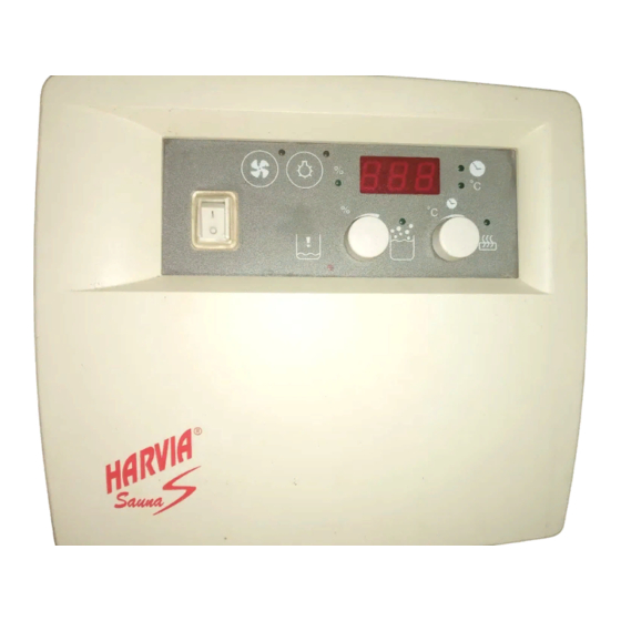
Page 5: Selecting Presetting Times And Duration Of Preset Time
2.1. Selecting presetting times and duration of 2.1. Wahl der Vorwahl- und der Einschaltzeit preset time Die Wahl der Zeiten kann erst erfolgen, wenn Times can only be selected when the heater and/or die Saunaofen- und/oder Verdampferfunktion steamer function is switched on (switches 2 and/or eingeschaltet ist (Schalter 2 und/oder 3). -
Page 6: Removing The Front
3.1. Removing the front 3.1. Entfernen des Deckels The front can be removed by inserting the tip of a Der Deckelteil löst sich am oberen Rand, wenn die Zunge, screwdriver in the clasp groove on top. See figure 3. die den Deckel blockiert, mit einem Schraubenzieher heruntergedrückt wird. -
Page 7: Mounting The Sensor Boxes
3.3. Mounting the sensor boxes 3.3. Montage der Fühlergehäuse Figure 6. The location of the CS10.5 control unit temperature and humidity sensor boxes when used with wall-mounted heaters. Abbildung 6. Ort für das Temperaturfühler- sowie Feuchtesensorgehäuse des Steuergerätes CS10.5 bei wandmodellen der Saunaöfen. -
Page 8: Electricial Connections
Figure 7. Reset button for overheating limiter Abbildung 7. Rücksetzknopf des Überhitzungsschutzes 3.4. Electrical Connections 3.4. Elektrische Anschlüsse 3-PHASE CS10.5+KKV50-90SE HEATER CABELS/KABEL 400V 3N~/230V 1N~ POWER HEATER POWER VAPORISER FUSES SAUNAOFEN TYPE LEISTUNG VERDAMPFER SICHERUNGEN LEISTUNG OFEN TYP (kW) (kW) - Page 9 1-PHASE CS10.5+KKV50-90SE 3-PHASE CS10.5+KKV50-90SEA (Automatic filling / Automatische Wasserbefüllung)
Need help?
Do you have a question about the CS10.5 and is the answer not in the manual?
Questions and answers