Riello Burners 40 Series Installation Instructions And Owner's Handbook
Hide thumbs
Also See for 40 Series:
- Installation, use and maintenance instructions (37 pages) ,
- Installation instructions and owner's handbook (21 pages)
Table of Contents
Advertisement
INSTALLATION INSTRUCTIONS AND OWNER'S HANDBOOK
CAUTION: All gas burners MUST be installed by trained and licensed technicians.
WARNING: Installation of this burner must conform with local codes or, in the absence of local codes, with
the Standard for the Installation of Domestic Gas Conversion Burners, ANSI Z21.8-1984, and Addendum,
Z21.8a-1989, and the National Fuel Gas code, ANSI Z223.1-1984, and CAN/CGA B149.1 &.2. If an external
electrical s ource is utilized, the conversion burner, when installed, must be electrically grounded in
accordance with local codes or, in the absence of local codes, with the national Electrical Code, ANSI/NFPA
No. 70-1990 and CSA Electrical Code.
Owner is required to retain this manual for future reference.
GAS SUPPLY PRESSURES
MANIFOLD PRESSURES
POWER
MOTOR
CONTROL MODULE
WARNING: If the information in these instructions is not followed exactly, a fire or
explosion may result causing property damage, personal injury or death.
Do not store or use gasoline or any other flammable vapours or liquid in the
vicinity of this or any other appliance.
WHAT TO DO IF YOU SMELL GAS:
1) Do not try to light any appliance.
2) Do not touch electrical switches; Do not use any phone in your building.
3) Immediately call your gas supplier from a neighbour's phone. Follow the gas
supplier's instructions.
4) If you cannot reach your gas supplier, call the fire department.
Installation and service must be performed by a qualified installer, service agency
or the gas supplier.
C6505020 STD G400 Manual Rev.5 -06/10/2002
40 SERIES GAS BURNER
MODEL 400 NATURAL GAS/PROPANE
TECHNICAL SPECIFICATIONS
FIRING RATE 170,000 TO 400,000 Btu/hr
NATURAL
MIN. 4" w.c.
MAX. 10" w.c.
MIN. 0.90" w.c.
MAX. 1.80" w.c.
120 VOLTS 60 Hz 1 PHASE
232T 2.2 AMPS 3250 RPM
525 SE/A ELECTRONIC
PROPANE
MIN. 8" w.c.
MAX. 13" w.c.
MIN. 1.04" w.c.
MAX. 3.04" w.c.
1
Advertisement
Table of Contents

Related Manuals for Riello Burners 40 Series


Summary of Contents for Riello Burners 40 Series
- Page 1 40 SERIES GAS BURNER MODEL 400 NATURAL GAS/PROPANE INSTALLATION INSTRUCTIONS AND OWNER’S HANDBOOK CAUTION: All gas burners MUST be installed by trained and licensed technicians. WARNING: Installation of this burner must conform with local codes or, in the absence of local codes, with the Standard for the Installation of Domestic Gas Conversion Burners, ANSI Z21.8-1984, and Addendum,...
-
Page 2: Table Of Contents
TABLE OF CONTENT PRINCIPAL BURNER COMPONENTS ....................4 DIMENSIONS............................4 ELECTRODE & FLAME PROBE ADJUSTMENTS ................5 TYPICAL GAS TRAIN LAYOUT......................6 INSTALLING THE BURNER ......................... 7 INSTALLATION OF SEDIMENT TRAP & BURNER SUPPLY ............9 FIELD WIRING DIAGRAM ........................10 FACTORY WIRING DIAGRAM...................... - Page 3 The following pages contain information, descriptions and diagrams for the proper installation and wiring of the burner. Please read carefully before attempting final installation. The responsibility for ensuring that this manual is complete rests with the holder of these instructions. SERIAL NUMBER IDENTIFICATION The Riello 15 character serial number, example, 99 A 8511111 00025, is identified as follows: 99 = last two digits of the year of manufacture;...
-
Page 4: Principal Burner Components
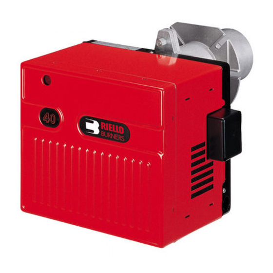
PRINCIPAL BURNER COMPONENTS 1. Air Damper (Optional Delete) 2. Air Gate Lock-screws 3. Wiring Terminal Block 4. Air Pressure Switch 5. Motor 6. Lockout Lamps and Reset Button 7. Cover Screw 8. Rubber Grommet 9. Capacitor BURNER DIMENSIONS Model 400 inches 10 5/16 1 3/8... -
Page 5: Electrode & Flame Probe Adjustments
UNIVERSAL MOUNTING FLANGE UNIVERSAL MOUNTING FLANGE DIMENSIONS inches 1 1/4 7/16 2 3/16 millimeters ELECTRODE AND FLAME PROBE ADJUSTMENTS IMPORTANT: Do not turn the ignition electrode. Leave it a s shown in the drawing. If the ignition electrode is put near the ionization probe, the amplifier of the control box may be damaged. C6505020 STD G400 Manual Rev.5 -06/10/2002... -
Page 6: Typical Gas Train Layout
TYPICAL GAS TRAIN LAYOUT RIELLO SUPPLIED FIELD SUPPLIED SEE GAS SUPPLY Ø RANGE NOTE: ITEMS 5,6 & 7 COMBINATION GAS VALVE(S) ASSEMBLIES MAY BE UTILIZED WHERE APPROVED. GAS TRAIN LEGEND 5) GAS APPLIANCE PRESSURE REGULATOR 1) GAS SUPPLY & FLOW DIRECTION OF GAS 6) SAFETY SHUTOFF GAS VALVE (VS) 24V OR 120V 2) GAS SUPPLY MAIN SHUTOFF MANUAL VALVE (FIELD OPERATED... -
Page 7: Installing The Burner
INSTALING THE BURNER Wet Base Illustration A) Burner Chassis B) Combustion Head Assembly 1. Locking Nut 2. Appliance Mounting Plate Insulation 3. Insulation Gasket Use this checklist prior to installation: 1) Check the input/output requirements of the appliance. We suggest that the appliance output should be approximately 85% of input (85% efficiency). - Page 8 STEP-BY-STEP PROCEDURE 1) Remove the burner from the carton, taking care not to lose any of the supplied accessories. Check for signs of physical damage. 2) Bolt the combustion head and burner to the appliance. Be sure to install the supplied mounting gasket.
-
Page 9: Installation Of Sediment Trap & Burner Supply
INSTALLATION OF SEDIMENT TRAP AND BURNER SUPPLY Gas piping to the burner must be inch minimum. Install only a full ported shutoff valve. The valve must be located outside the appliance jacket, and the pressure gauge port must be accessible. PRESSURE TEST-OVER PSIG. -
Page 10: Field Wiring Diagram
FIELD WIRING DIAGRAM 120 V controlled 24 V controlled Optional 24 V controlled Green Green white 24 Volts 24 Volt Relay * black Gnd. operating operating Gnd. control control service service switch switch 120 Volts 60 Hz. FACTORY WIRING DIAGRAM RIELLO POWER GAS BURNER MODELS G120, G200 &... -
Page 11: Setting Up The Burner
burner lockout occur, the 525 SE CONTROL BOX will supply a power source of 120 Vac to the connection terminal. The maximum allowable current draw on this terminal is 1 A. IMPORTANT Terminal 4 is to be used only for the connection of a remote sensing device. If a neutral or ground lead is attached to terminal 4 the control box will be damaged should lockout occur SETTING UP THE BURNER After burner output has been determined, use TABLE 1 below AS AN INITIAL GUIDE for burner settings. -
Page 12: Operating Faults
THERE IS NO SUBSTITUTE FOR PROPER COMBUSTION TESTING OPERATING FAULTS The integrated control system is self checking. The cycle from start up to flame establishment, takes approximately 70 seconds. The burner will go into lockout under the following circumstances: a) Burner fails to ignite. b) The ionization probe is grounded. -
Page 13: Combustion Head Setting
All settings in table 2 are obtained with Table 2 zero (0) pressure in the combustion Riello 40 Model 400 N/P zone and at normal operating Air Gate Settings temperatures. i.e., steady state hot Burner Output Air Gate Setting conditions. Btu/hr x 1000 Natural Propane... -
Page 14: Manifold Pressures
MANIFOLD PRESSURES Manifold gas pressure for various firing rates must be set by adjusting the gas regulator of the gas valve. To check manifold gas pressure, attach a manometer to the manifold test point, shown on typical gas train layout on page 6. -
Page 15: Combustion Checks
Any change from zero (0) pressure in the combustion zone will affect the Btu output of the burner. To supply the required input to the appliance, manifold pressure will have to be adjusted to compensate for this condition. COMBUSTION CHAMBER SIZE Recommended Minimum Sizes INPUT (000's) BTUH NOTES:... -
Page 16: Starting Cycle
Burner Start-up Cycle Ionization Current Check PROBLEM SOLVING GUIDE Burner starting difficulties and their causes: 1) The burner goes through the prepurge period normally. The flame ignites, but the burner goes to lockout within five seconds. a) The phase/neutral lines are reversed. b) The wiring to ground is absent or ineffective. -
Page 17: Owner Information & Routine Maintenance
3) The burner does not start when the thermostat calls for heat. The gas pressure switch (if supplied) does not close contact due to low gas pressure. The 24 volt switching relay is defective. The line switch is off. There is a blown fuse in the panel. Terminals on the control module are bent or loose The motor is defective. -
Page 18: Installation Data
3) Check the flame sensor rod (ionization rod) for dirt or carbon build up. Clean, adjust, or replace as necessary. 4) Check manifold gas pressure. 5) Check all burner adjustments. 6) Generally clean all exposed parts and components. 7) Do a complete combustion test with the burner cover in place and the air gate locking screws secure. Your Riello 40 gas burner is only part of your heating system. -
Page 19: Spare Parts List
GAS BURNER SYSTEM RIELLO 40 N400 SPARE PARTS REVISED: 10/01 SPARE SPARE PARTS PARTS DESCRIPTION DESCRIPTION CODE CODE 3007238 Burner back cover 3950371 Short combustion head (279T1) C7020008 Air switch 3006696 Drawer assembly elbow 3001162 Primary control box 525 SE/A 3007275 Electrode assembly 3002307... -
Page 20: Spare Parts Diagram
C6505020 STD G400 Manual Rev.5 -06/10/2002... -
Page 21: Burner Start-Up Form
35 Pond Park Rd. 2165 Meadowpine Blvd. Hingham, MA 02043 Mississauga,On L5H 3R2 Phone: 781-749-8292 Phone: 905-542-0303 Toll Free: 800-992-7637 Toll Free: 800-387-3898 Fax: 781-740-2069 Fax: 905-542-1525 BURNER START- UP FORM Burner S/N. or Model: Appliance: Installer name: Company: Installation date: Address: Phone: Fax:... - Page 22 35 Pond Park Road 2165 Meadowpine Blvd Hingham, MA 02043 Mississauga, ON L5N 6H6 Phone 781-749-8292 Phone 905-542-0303 Toll Free 800-992-7637 Toll Free 800-387-3898 Fax 781-740-2069 Fax 905-542-1525 www.riellousa.com www.riellocanada.com Technical Support Hotline 1-800-4-RIELLO 1-800-474-3556 C6505020 STD G400 Manual Rev.5 -06/10/2002...
Need help?
Do you have a question about the 40 Series and is the answer not in the manual?
Questions and answers