Advertisement
Quick Links
Istruzioni per installazione, uso e manutenzione
Montage und Bedienungs Anleitung
Installation, use and maintenance instructions
Manuel d'entretien
Bruciatori di gas
I
Gasbrenner
D
Gas burners
GB
Brûleurs gaz
F
Funzionamento modulante
Modulierender Betrieb
Modulating operation
Fonctionnement modulant
CODICE - CODE
3786200
3786205
3786210
3786215
3786300
3786305
3786310
3786315
MODEL - MODELE
MB8SE
MB10SE
TIPO - TYP
TYPE - TYPE
842 T1
842 T1
844 T1
844 T1
844 T1
2915743 (4) - 11/2007
Advertisement
Chapters

Related Manuals for Riello Burners MB8SE


Summary of Contents for Riello Burners MB8SE
-
Page 1: Table Of Contents
Brûleurs gaz Funzionamento modulante Modulierender Betrieb Modulating operation Fonctionnement modulant MODELLO - MODELL TIPO - TYP CODICE - CODE MODEL - MODELE TYPE - TYPE 3786200 MB8SE 842 T1 3786205 MB8SE 842 T1 3786210 MB8SE 842 T1 3786215 MB8SE 842 T1... -
Page 3: Modello - Modell
Pressione sonora misurata nel laboratorio combustione del costruttore, con bruciatore funzionante su caldaia di prova, alla potenza massima. ACCESSORI (su richiesta) KIT PER FUNZIONAMENTO A GPL: il kit consente ai bruciatori MB8SE - MB10SE di bruciare GPL. BRUCIATORE MB8SE MB10SE POTENZA 1300 ÷... -
Page 4: Dati Tecnici
3 / 230V / 50Hz Tensione ausiliari : 230/50/60 230V / 50-60Hz 110/50/60 110V / 50-60Hz 3/400/50 230/50/60 DESIGNAZIONE BASE DESIGNAZIONE ESTESA ELENCO MODELLI DISPONIBILI Designazione Codice MB8SE 3/400/50 230/50/60 3786200 MB8SE 3/230/50 230/50/60 3786205 MB8SE 3/400/50 230/50/60 3786210 MB8SE... -
Page 5: Mb8Se 842 T1
Druck am Anschluß des Druckwächters 26)(A)S.12 bei druckloser Brennkammer und bei Höchstleistung des Brenners. Schalldruck, im Brennprüflabor des Herstellers mit Brenner auf Prüfkessel bei Höchstleistung. ZUBEHÖR (auf Wunsch) KIT FÜR FLÜSSIGAS-BETRIEB: Der Kit erlaubt den Brennern MB8SE - MB10SE Flüssiggas zu brennen. BRENNER MB8SE MB10SE LEISTUNG 1300 ÷... -
Page 6: Mb10Se
3 / 230V / 50Hz Spannung der Hilfskreise : 230/50/60 230V / 50-60Hz 110/50/60 110V / 50-60Hz 3/400/50 230/50/60 BASISBEZEICHNUNG ERWEITERTE BEZEICHNUNG VERZEINIS DER MODELLE Bezeichnung Code MB8SE 3/400/50 230/50/60 3786200 MB8SE 3/230/50 230/50/60 3786205 MB8SE 3/400/50 230/50/60 3786210 MB8SE... -
Page 7: Technical Data
Pressure at pressure switch test point 26)(A)p.12 with zero pressure in the combustion chamber and maximum burner output. Sound pressure measured in manufacturer’s combustion laboratory, with burner operating on test boiler and at maximum rated output. ACCESSORIES (optional) KIT FOR LPG OPERATION: The kit allows the MB8SE - MB10SE burners to operate on LPG. BURNER MB8SE MB10SE OUTPUT 1300 ÷... - Page 8 INDICE INHALT Dati tecnici ........pagina 4 Technische Angaben .
-
Page 9: List Of Available Models
3 / 230V / 50Hz Auxiliary voltage : 230/50/60 230V / 50-60Hz 110/50/60 110V / 50-60Hz 3/400/50 230/50/60 BASIC DESIGNATION EXTENDED DESIGNATION LIST OF AVAILABLE MODELS Designation Code MB8SE 3/400/50 230/50/60 3786200 MB8SE 3/230/50 230/50/60 3786205 MB8SE 3/400/50 230/50/60 3786210 MB8SE... -
Page 10: Données Techniques
Pression acoustique mesurée dans le laboratoire combustion du constructeur, le brûleur fonctionnant sur une chaudière d’essai à la puissance maximum. ACCESSOIRES (sur demande) KIT POUR FONCTIONNEMENT AU GPL: Le kit permet aux brûleurs MB8SE - MB10SE de fonctionner au GPL. BRÛLEUR MB8SE MB10SE PUISSANCE 1300 ÷... -
Page 11: Modèles Disponibles
3 / 230V / 50Hz Tension auxiliaires : 230/50/60 230V / 50-60Hz 110/50/60 110V / 50-60Hz 3/400/50 230/50/60 DESIGNATION BASE DESIGNATION ELARGIE MODELES DISPONIBLES Designation Code MB8SE 3/400/50 230/50/60 3786200 MB8SE 3/230/50 230/50/60 3786205 MB8SE 3/400/50 230/50/60 3786210 MB8SE 3/230/50... -
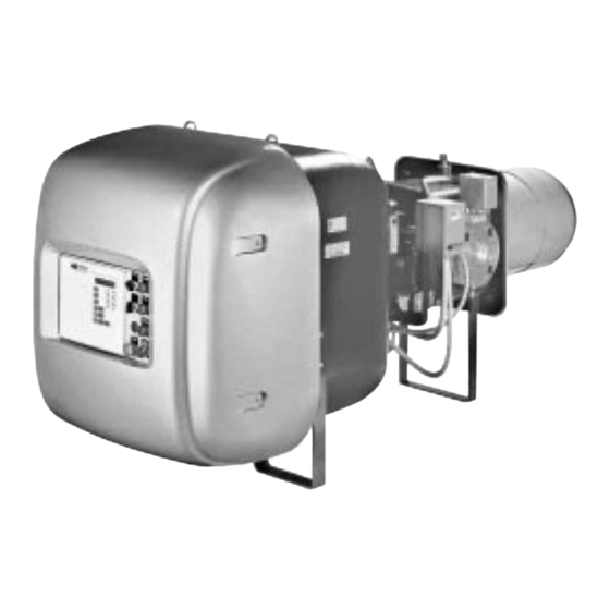
Page 12: Descrizione Bruciatore
DESCRIZIONE BRUCIATORE (A) - (B) ALIMENTAZIONE COMBUSTIBILE DESTRA Anelli di sollevamento BRENNSTOFFVERSORGUNG RECHTS Girante RIGHT FUEL SUPPLY Motore ventilatore ALIMENTATION DU COMBUSTIBLE A DROITE Servomotore serranda aria Servomotore regolatore gas Testa di combustione Elettrodi di accensione Disco di stabilità fiamma D2096 Quadro di controllo (vedere pag. -
Page 13: Burner Description
BRENNERBESCHREIBUNG (A) - (B) BURNER DESCRIPTION (A) - (B) DESCRIPTION BRULEUR (A) - (B) Heberinge Lifting eyebolts Anneaux de soulèvement Gebläserad Turbine Gebläsemotor Fan motor Moteur ventilateur Luftklappestellantrieb Air gate valve servomotor Servomoteur volet d’air Stellantrieb für Gasregler Servomotor for butterfly valve setting Servomoteur régulateur gaz Flammkopf Combustion head... -
Page 14: Descrizione Quadro Elettrico
DESCRIZIONE QUADRO ELETTRICO (A) QUADRO ELETTRICO - SCHALTTAFEL Portafusibili motore ventilatore PANEL BOARD - TABLEAU ELECTRIQUE Portafusibile per ausiliari Relè Avviatore stella/triangolo Selettore acceso-spento Segnalazione luminosa tensione ausiliari Dispositivo di taratura a camma elettronica Segnalazione luminosa bruciatore in marcia Dadi per la rimozione del pannello porta camma elettronica 10 Segnalazione luminosa blocco motore 11 Segnalazione luminosa blocco bruciatore e... -
Page 15: Description Of Panel Board
BESCHREIBUNG DER SCHALTTAFEL (A) DESCRIPTION OF PANEL BOARD (A) DESCRIPTION TABLEAU ELECTRIQUE (A) 1 Sicherungshalter Gebläsemotor Fan motor fuse holder Porte-fusibles moteur ventilateur 2 Sicherungshalter für Hilfskreise Fuse holder for accessories Porte-fusibles pour relais auxiliaires 3 Relais Relay Relais 4 Stern-Dreieck-Anlasser Star-powered/delta-powered starter Démarreur étoile/triangle 5 Wählschalter Ein-Aus... -
Page 16: Ingombro
La POTENZA MASSIMA va scelta entro l'area tratteggiata del diagramma. La POTENZA MINIMA non deve essere infe- riore al limite minimo del diagramma: MB8SE = 1330 kW MB10SE = 1185 kW Attenzione: il CAMPO DI LAVORO è stato rica- vato alla temperatura ambiente di 20 °C, alla... -
Page 17: Caldaia Di Prova
Zone im Diagramm gewählt. rieure à la limite minimum du diagramme: MINIMUM OUTPUT must not be lower than the Die MINDESTLEISTUNG soll nicht niedriger MB8SE = 1330 kW minimum limit shown in the diagram: sein als die Mindestgrenze des Diagramms:... -
Page 18: Installazione
INSTALLAZIONE PIASTRA CALDAIA - KESSELPLATTE BOILER PLATE - PLAQUE CHAUDIERE PIASTRA CALDAIA (A) Forare la piastra di chiusura della camera di combustione come in (A). La posizione dei fori filettati può essere tracciata utilizzando lo schermo termico a corredo del bruciatore. MB8 - 10SE M 20 LUNGHEZZA BOCCAGLIO (B) -
Page 19: Installation
INSTALLATION INSTALLATION INSTALLATION KESSELPLATTE (A) BOILER PLATE (A) PLAQUE CHAUDIERE (A) Die Abdeckplatte der Brennkammer wie in (A) Drill the combustion chamber locking plate as Percer la plaque de fermeture de la chambre de gezeigt vorbohren. Die Position der Gewindebo- shown in (A). -
Page 20: Posizione Elettrodi
Allo scopo di sfruttare la massima velocità dell’aria in uscita dalla testa, che si ottiene con la massima apertura delle serrande aria ma con la MB8SE MB10SE minima apertura della testa, inizialmente fissare Foro - Loch Potenza - Leistung... -
Page 21: Position Of Electrodes
POSITION DER ELEKTRODEN (A) POSITION OF ELECTRODES (A) POSITION DES ELECTRODES (A) Kontrollieren Sie, ob die Elektroden wie in Abb. Make sure that the electrodes are positioned as Contrôler si les électrodes sont positionnées (A) ausgerichtet sind. shown in figure (A). comme sur la fig. -
Page 22: Regolazioni Prima Dell'accensione
REGOLAZIONI PRIMA DELL’ACCEN- SIONE La regolazione della testa di combustione è già stata descritta a pag. 20. Altre regolazioni da fare sono: - Aprire le valvole manuali poste a monte della rampa del gas. - Regolare il pressostato gas di minima all'inizio scala. -
Page 23: Adjustment Before First Firing
EINSTELLUNGEN VOR DER ZÜNDUNG ADJUSTMENTS BEFORE FIRST FIRING REGLAGES AVANT L'ALLUMAGE Die Einstellung des Flammkopfs ist bereits auf Adjustment of the combustion head has been Le réglage de la tête de combustion a déjà été Seite 21 beschrieben worden. illustrated on page 21. décrit page 21. -
Page 24: Linea Alimentazione Gas
LEGENDA TABELLA (C) Brûleur Rampe gaz Papillon gaz C.T.= Dispositivo controllo tenuta valvole gas 14 (P1) VPS: - = Rampa priva del dispositivo di con- MB8SE MB10SE MBC-1200 MBC-1900 MBC-3100 MBC-5000 G 20 G 25 trollo tenuta; dispositivo che può... -
Page 25: Gas Line
GASZULEITUNG (A) GAS LINE (A) LIGNE ALIMENTATION GAZ (A) • Die Gasarmatur ist über Flansch 2), Dich- • The gas train must be connected to the gas • La rampe du gaz doit être reliée au raccord attachment 1)(A), using flange 2), gasket 3) du gaz 1)(A), par la bride 2), le joint 3) et les tung 3) und Schrauben 4), zur Brenneraus- and screws 4) supplied with the burner. -
Page 26: Pressostato Aria
PRESSOSTATO ARIA (A) - PRESSOSTATO ARIA - LUFT-DRUCKWÄCHTER CONTROLLO CO AIR PRESSURE SWITCH - PRESSOSTAT AIR La regolazione del pressostato aria, inizialmente regolato ad inizio scala, va eseguita dopo aver effettuato tutte le regolazioni di combustione del bruciatore dal minimo al massimo della modula- zione. -
Page 27: Air Pressure Switch
LUFTDRUCKWÄCHTER (A) - AIR PRESSURE SWITCH (A) - PRESSOSTAT DE L'AIR (A) - CO-ÜBERWACHUNG CO CHECK CONTROLE CO Die Einstellung des Luftdruckwächters, anfäng- The air pressure switch, initially set at the begin- Le réglage du pressostat air, réglé initialement lich auf Skalabeginn geregelt, erfolgt nach ning of the scale, should be adjusted after having au début d’échelle, est effectué... -
Page 28: Manutenzione
MANUTENZIONE CELLULA UV - UV ZELLE Combustione UV CELL - DETECTEUR UV Effettuare l'analisi dei gas di scarico della com- bustione. Gli scostamenti significativi rispetto al precedente controllo indicheranno i punti dove più attenta dovrà essere l'operazione di manu- tenzione. Fughe di gas Controllare che non vi siano fughe di gas sul condotto contatore-bruciatore. -
Page 29: Maintenance
WARTUNG MAINTENANCE ENTRETIEN Verbrennung Combustion Combustion Die Abgase der Verbrennung analysieren. The optimum calibration of the burner requires Pour obtenir un réglage optimal du brûleur, il Bemerkenswerte Abweichungen im Vergleich an analysis of the flue gases. Significant differ- faut effectuer l'analyse des gaz d'échappement zur vorherigen Überprüfung zeigen die Stelle ences with respect to the previous measure- de la combustion à... -
Page 30: Sistema Di Regolazione Aria/Combustibile E Modulazione Potenza
SISTEMA DI REGOLAZIONE ARIA/COM- Mini MK5 EVO BUSTIBILE E MODULAZIONE POTENZA • GENERALITÀ Il sistema di regolazione aria/combustibile, e di modulazione della potenza, che equipaggia i ENTER bruciatori serie Modubloc realizza, in un unico MEMORY dispositivo di controllo, una serie di funzioni inte- grate per la totale ottimizzazione energetica e INTER operativa del bruciatore, sia in caso di funziona-... -
Page 31: Air/Fuel Control And Power Modulation System
SYSTEM FÜR DIE LUFT-/BRENNSTOFF- AIR/FUEL CONTROL POWER SYSTEME DE REGLAGE AIR/ COMBUS- REGELUNG UND DIE LEISTUNGSMO- MODULATION SYSTEM TIBLE ET MODULATION DE LA PUIS- DULATION SANCE • GENERAL INFORMATION The air/fuel and power modulation system • ALLGEMEINES • GENERALITES installed on Modubloc burner series provides, Das System für die Luft-/Brennstoffregelung und Le système de réglage air/ combustible et de in a single control device, a set of integrated... - Page 32 Nella modalità DISPLAY STATUS viene visualiz- zato il valore richiesto (RE = required) e quello attuale (AC = actual). Per impostare il valore richiesto (set point) di TASTI Mini MK5 EVO - TASTEN Mini MK5 EVO pressione/temperatura, in modalità DISPLAY BUTTONS Mini MK5 EVO - BOUTONS Mini MK5 EVO STATUS, usare i pulsanti situati...
- Page 33 In der Modalität DISPLAY STATUS wird der In DISPLAY STATUS mode, the required value Dans la modalité DISPLAY STATUS, la valeur geforderte Wert (RE = required) und der aktuelle (RE = required) and current value (AC = actual) demandée (RE = required) et celle actuelle (AC Wert (AC = actual) angezeigt.
- Page 34 Modulazione manuale (per Mini MK5 EVO) Premere il pulsante HAND per aumentare o diminuire la potenza e operare sui tasti situati più in basso. Modulazione manuale (per Mini MK6) Selezionato sul selettore di scelta BURNER MODULATION la posizione MAN per aumen- tare o diminuire la potenza, operare sui tasti situati più...
- Page 35 Manuelle Modulation (für Mini MK5 EVO) Manual modulation (for Mini MK5 EVO) Modulation manuelle (pour Mini MK5 EVO) Die Taste HAND drücken, um die Leistung zu Press the HAND button to increase or decrease Appuyer sur le bouton HAND pour augmen- erhöhen oder zu verringern und die Tasten ter ou diminuer la puissance et opérer sur les the power and work on the keys...
-
Page 36: Appendice (Fs1) Schema Quadro Elettrico
Appendice - Anhang - Appendix - Annexe FS1 VERSION Schema quadro elettrico - Schaltplan Layout of electric panel board - Schéma tableau électrique INDICE - INHALT - CONTENTS - INDEX Indicazione riferimenti - Bezugangabe References layout - Indication références MB 8 SE Schema unifilare di potenza - Eindrahtiges Leistungsschema Layout of unifilar output - Schéma unifilaire de puissance MB 10 SE... - Page 37 MB 8 SE FS1...
- Page 38 MB 10 SE FS1...
-
Page 46: Appendice (Fs2) Schema Quadro Elettrico
Appendice - Anhang - Appendix - Annexe FS2 VERSION Schema quadro elettrico - Schaltplan Layout of electric panel board - Schéma tableau électrique INDICE - INHALT - CONTENTS - INDEX Indicazione riferimenti - Bezugangabe References layout - Indication références MB 8 SE Schema unifilare di potenza - Eindrahtiges Leistungsschema Layout of unifilar output - Schéma unifilaire de puissance MB 10 SE... - Page 47 MB 8 SE FS2...
- Page 48 MB 10 SE FS2...
- Page 57 LEGENDA SCHEMI ELETTRICI ZEICHENERKLÄRUNG SCHEMEN - Camma elettronica - Elektronischer Nocken - Dispositivo modulazione esterna - Externe Modulation-Vorrichtung - Sonda di pressione - Druckfühler - Sonda di temperatura - Temperaturfühler - Data Transfert Interface - Data Transfert Interface - Analizzatore di combustione - Verbrennungsanalysator - Relè...
- Page 58 KEY TO ELECTRICAL LAYOUT LÉGENDE SCHÉMAS ELECTRIQUE - Electronic cam - Came électronique - External modulation device - Dispositif modulation externe - Pressure probe - Sonde de pression - Temperature probe - Sonde de température - Data Transfert Interface - Data Transfert Interface - Combustion analyser - Analyseur de combustion - Fan motor thermal cut-out...
-
Page 59: Moduli Aggiuntivi
MODULI AGGIUNTIVI (optional) ZUSATZMODULE (Optionals) Mit den Autoflame Systemen können Anlagen mit einem oder mehre- I sistemi Autoflame consentono di gestire impianti con uno o più bru- ren Brennern überwacht und örtlich oder fern gesteuert werden. ciatori permettendo supervisioni e controlli locali e remoti. Mit den zahlreichen Kombinationen der hier folgend beschriebenen Le combinazioni dei moduli aggiuntivi Autoflame di seguito descritti e Autoflame Zusatzmodule und der Anschlusssysteme RS232, RS422,... -
Page 60: Modules Supplémentaires
ADDITIONAL MODULES (optional) MODULES SUPPLÉMENTAIRES (en option) Les systèmes Autoflame permettent de gérer les installations avec un Autoflame systems allow running installations with one or more burn- ou plusieurs brûleurs pour la supervision et les contrôles locaux ou à ers, giving local and remote supervision and control. distance. - Page 64 RIELLO S.p.A. I-37045 Legnago (VR) Tel.: +39.0442.630111 http:// www.rielloburners.com Con riserva di modifiche - Änderungen vorbehalten! - Subject to modifications - Sous réserve de modifications...
Need help?
Do you have a question about the MB8SE and is the answer not in the manual?
Questions and answers