
Related Manuals for Taylor 142


Summary of Contents for Taylor 142
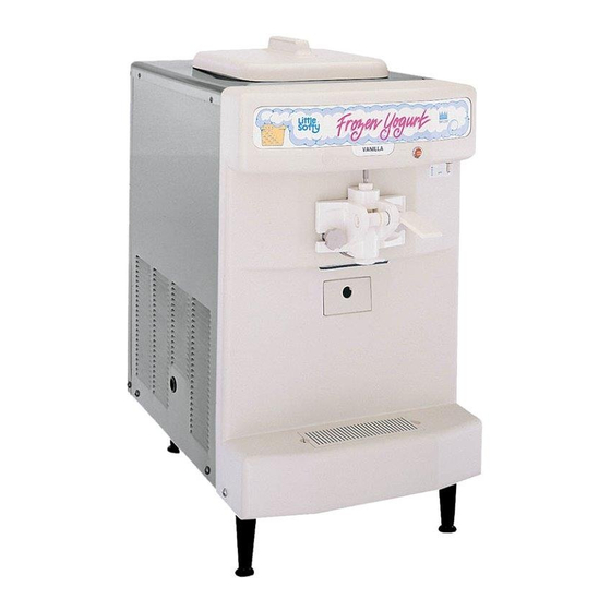
- Page 1 OPERATOR’S MANUAL Model 142 Soft Serve Freezer Original Operating Instructions 039709- M 3/00 (Original Publication) (Updated 8/3/15)
- Page 2 Phase Maximum Fuse Size: Minimum Wire Ampacity: E 2000 Taylor Company 039709- M Any unauthorized reproduction, disclosure, or distribution of copies by any person of any portion of this work may be a violation of Copyright Law of the United States of America and other countries, could result in the awarding of Statutory Damages of up to $250,000 (17 USC 504) for infringement, and may result in further civil and criminal penalties.
-
Page 3: Table Of Contents
............. . Table of Contents Model 142... - Page 4 Note: Only instructions originating from the factory or its authorized translation representative(s) are considered to be the original set of instructions. E 2000 Taylor Company (Original Publication) (Updated August, 2015) 039709- M...
-
Page 5: To The Installer
Failure to service of Taylor equipment. follow this instruction may result in electrocution. Only authorized Taylor service personnel should perform installation and repairs on the equipment. Authorized service personnel should consult This unit must be installed on a level surface OSHA Standard 29CFRI910.147 or the... -
Page 6: Electrical Connections
The installation location is marked by the equipotential bonding symbol (5021 of IEC 60417-1) on both the removable panel and the equipment’s frame. 101111 To the Installer Model 142... -
Page 7: Electrical Hook- Up Installation
Remove the factory- installed cord and strain relief bushing. Taylor reminds technicians to be cautious of Route incoming permanent wiring through 7/8” government laws regarding refrigerant recovery, (22 mm) hole in base pan. -
Page 8: To The Operator
The unauthorized use of Note: Your Taylor warranty is valid only if the parts are alternate refrigerants will void your Taylor compressor authorized Taylor parts, purchased from the local warranty. -
Page 9: Safety
We, at Taylor Company, are concerned about the safety of the operator when he or she comes in contact with the freezer and its parts. Taylor has gone to extreme efforts to design and manufacture built- in DO NOT operate the freezer unless it is safety features to protect both you and the service properly grounded. - Page 10 1.6 meters from the floor. 130211 Safety Model 142...
-
Page 11: Operator Parts Identification
HANDLE- DRAW 024762 BEATER A. X24689 O- RING- 3/4 OD X .103W 015835 BEARING- FRONT 023262 O- RING- 7/8 OD X .103W 014402 O- RING- 2- 3/4 OD X .139W 019998 VALVE- DRAW 024763 140407 Model 142 Operator Parts Identification... -
Page 12: Important: To The Operator
To better communicate in the International arena, the words on many of our operator switches and buttons have symbols to indicate their functions. Your Taylor equipment is designed with these International Indicator Light - MIX LOW symbols. -
Page 13: Standby Switch
This will cause damage to the beater assembly and to the freezer door. Depending upon the product being run, you may wish to contact your local authorized Taylor Distributor to make a slight adjustment in the feed tube. Figure 4... -
Page 14: Operating Procedures
Section 6 Operating Procedures The Model 142 has a 1.5 quart (1.4 liter) capacity Step 2 freezing cylinder. The mix flows from the hopper to the Insert the beater assembly and allow the drive shaft to freezing cylinder through a feed tube. The mix flow is travel through the rear shell bearing at the back of the controlled by gravity. -
Page 15: Model
Install the draw valve. Slide the two o- rings into the flanged edge is against the door. Place the white grooves on the draw valve and lubricate with Taylor plastic guide bearing on the end of the baffle rod. Do Lube. - Page 16 Note: The draw valve is installed correctly when the Slide the o- ring into the groove on the draw valve slotted opening in the draw valve is visible through the handle and lubricate with Taylor Lube. “window” of the freezer door. Figure 14...
-
Page 17: Sanitizing
Figure 17 Step 10 Lay the feed tube and mix level float in the bottom of the mix hopper. Figure 19 090421 Model 142 Operating Procedures... - Page 18 Place the mix level float on the mix level float stem. Figure 21 Step 4 Place the toggle switch in the WASH position. This will cause the sanitizing solution in the freezing cylinder to be agitated. Allow to agitate for five minutes. Figure 23 Operating Procedures Model 142...
-
Page 19: Priming
Slide the rear drip pan into the hole in the front panel. Figure 25 Step 3 Place the toggle switch in the AUTO position. When the unit cycles off, the product will be ready to serve. Figure 28 Model 142 Operating Procedures... -
Page 20: Standby
To remove the unit from the STANDBY mode, place Necessary brushes (provided with freezer) the power switch in the AUTO position, and press the Cleaner standby button. The light will extinguish, indicating that Single service towels the unit has resumed the normal operating mode. Operating Procedures Model 142... -
Page 21: Draining Product From The Freezing Cylinder
Repeat this procedure until the rinse water being of the beater assembly should be replaced or drawn from the freezing cylinder is clear. lubricated properly. 140718 Model 142 Operating Procedures... -
Page 22: Brush Cleaning
Figure 31 Step 4 Remove the large o- ring, the front bearing, and the Step 7 guide bearing from the back of the freezer door. Clean all exterior surfaces of the freezer. 120529 Operating Procedures Model 142... -
Page 23: Important: Operator Checklist
DO NOT Never use screwdrivers or other metal prime the machine with rerun. When using probes to clean between the fins. 080110 Model 142 Important: Operator Checklist... -
Page 24: Winter Storage
All parts should be thoroughly cleaned of dried Disconnect the freezer from the main power source to mix or lubrication accumulations which attract mice prevent possible electrical damage. and other vermin. Your local Taylor Distributor can perform this service for you. Important: Operator Checklist Model 142... -
Page 25: Troubleshooting Guide
Reset the toggle switch. beater motor. Place toggle switch in the AUTO position. 3. Product is too stiff. a. The temperature control is a. Call service technician. - - - set too cold. Model 142 Troubleshooting Guide... - Page 26 Worn rear shell bearing. b. Contact service - - - technician. c. Incorrect lubricant. c. Use food grade lubricant (example: Taylor Lube). d. Inadequate lubrication of d. Lubricate properly. beater drive shaft. 7. Draw valve leaking. a. Incorrect lubricant.
-
Page 27: Parts Replacement Schedule
Draw Valve Handle O- Ring Black Bristle Brush, 1” x 2” Inspect & Minimum Replace if Necessary Double Ended Brush Inspect & Minimum Replace if Necessary White Bristle Brush, 3” x 7” Inspect & Minimum Replace if Necessary 120430 Model 142 Parts Replacement Schedule... -
Page 28: Section 10 Limited Warranty On Equipment
Taylor, through an authorized Taylor distributor or service agency, will provide a new or re- manufactured part, at Taylor’s option, to replace the failed defective part at no charge for the part. Except as otherwise stated herein, these are Taylor’s exclusive obligations under this limited warranty for a Product failure. - Page 29 LEGAL REMEDIES The owner must notify Taylor in writing, by certified or registered letter to the following address, of any defect or complaint with the Product, stating the defect or complaint and a specific request for repair, replacement, or other correction of the Product under warranty, mailed at least thirty (30) days before pursuing any legal rights or remedies.
-
Page 30: Limited Warranty On Parts
Taylor warrants the Parts against failure due to defect in materials or workmanship under normal use and service as follows. All warranty periods begin on the date of original installation of the Part in the Taylor unit. If a Part fails due to defect during the applicable warranty period, Taylor, through an authorized Taylor distributor or service agency, will provide a new or re- manufactured Part, at Taylor’s option, to replace the failed defective Part at no... - Page 31 Parts or the units in which they are installed repaired or altered in any way so as, in the judgment of Taylor, to adversely affect performance, or normal wear or deterioration.
- Page 32 LEGAL REMEDIES The owner must notify Taylor in writing, by certified or registered letter to the following address, of any defect or complaint with the Part, stating the defect or complaint and a specific request for repair, replacement, or other correction of the Part under warranty, mailed at least thirty (30) days before pursuing any legal rights or remedies.
Need help?
Do you have a question about the 142 and is the answer not in the manual?
Questions and answers