
Related Manuals for Insignia NS-PMM6230


Summary of Contents for Insignia NS-PMM6230
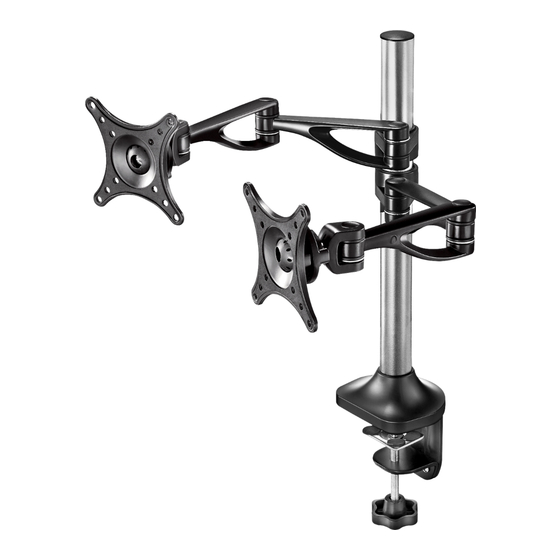
- Page 1 ASSEMBLY GUIDE Dual Screen Desktop Monitor Mount NS-PMM6230 Before using your new product, please read these instructions to prevent any damage.
-
Page 2: Table Of Contents
Contents Introduction ..................3 IMPORTANT SAFETY INSTRUCTIONS . -
Page 3: Introduction
NS-PMM6230 Introduction Congratulations on your purchase of a high-quality Insignia product. Your NS-PMM6230 represents the state of the art in monitor mount design and is designed for reliable and trouble-free performance. IMPORTANT SAFETY INSTRUCTIONS 1 Make sure these instructions are read and completely understood before attempting installation. If you are unsure of any part of this installation, please contact a professional installer for assistance. -
Page 4: Dimensions
Dimensions Max. 27.6" (70 cm) 6" (15.1 cm) 6" (15.1 cm) ±90° 20.1" (51 cm) www.insigniaproducts.com... -
Page 5: Package Contents
NS-PMM6230 Package contents Parts Make sure that you have all the parts necessary to assemble your new monitor mount: PART QTY. PART QTY. Monitor plate and support arm Tube bottom cover Fixed ring Base support plate Arm cable clips Base support (clamp mounting) -
Page 6: Vesa Mount Patterns
Hardware Make sure that you have all the hardware necessary to assemble your new monitor mount: Note: You may not use all the included hardware. Ltr. HARDWARE QTY. Ltr. HARDWARE QTY. M4 × 12 mm mounting screw M10 × 20 mm screw M5 ×... -
Page 7: Step 2-Option 1: Attaching Your Monitor Mount To A Desktop Edge
NS-PMM6230 STEP 2-Option 1: Attaching your monitor mount to a desktop edge Notes: • Make sure that the tabletop or desktop is square or rectangular. Your mount may not fit securely to an oval or irregularly shaped surface. • Make sure that the tabletop or desktop thickness is between .8 and 2.2 inches (2 and 5.5 cm). - Page 8 3 Attach the base support (12) to the base support plate using the two M6 × 10 mm screws (G), then tighten the screws with the 4 × 4 Allen wrench (I). 4 Slide the decorative cover (8) all the way down the support tube until it covers the base support plate. 5 Loosen the knob on the bottom of the base support, slide the clamp assembly onto the edge of the desk, then tighten the knob.
-
Page 9: Step 2-Option 2: Attaching Your Mount Through A Desktop Grommet Hole
NS-PMM6230 STEP 2-Option 2: Attaching your mount through a desktop grommet hole Notes: • Make sure that the grommet hole is between .5 and 2 inches (1.2 and 5.0 cm). • Make sure that the tabletop or desktop thickness is between 1 and 2.8 inches (2.5 and 7 cm). - Page 10 4 Slide the decorative cover (8) all the way down the support tube until it covers the base support plate. 5 Attach the bottom plate (14) to the bottom of the base plate using the four screws you removed in step 1. 6 Cover the screw heads with the padded mat feet (15), then place the top mounting assembly over the grommet hole.
-
Page 11: Step 3: Attaching The Monitor Support Arms
NS-PMM6230 STEP 3: Attaching the monitor support arms As you decide where to position the monitor support arms, remember the tops of the monitors should be level with your eyes. Note: You need a Phillips screwdriver for this step. 1 Make sure that the wider opening on one of the arm support rings (5) is facing up, then place the ring on the support tube at the level you want the mounting plate and support arm. - Page 12 4 Slide the other monitor plate and support arm assembly (1 or 4) onto the support tube, making sure that the curved portions of the arm are pointed up. 5 Make sure that the wider opening on one of the arm support rings (5) is facing up, then place the ring on the support tube at the level you want the mounting plate and support arm.
-
Page 13: Step 4: Attaching The Monitors
NS-PMM6230 STEP 4: Attaching the monitors Depending on the VESA screw holes on the back of your monitors, you need to use the M4 × 12 mm mounting screws (A) or M5 × 12 mm mounting screws (B). 1 Determine which mounting screws you need (A or B) by hand-threading a screw in a VESA screw hole. Do not force the screw to fit. -
Page 14: Step 6: Managing Cables
STEP 6: Managing cables 1 Align any cables to the back side of the monitor arms, then secure them in place with the arm cable clips (3). 2 Align the cables to the back side of the support tube, then secure them in place with the cable support clips (7). Specifications Monitor size 10 to 27 inch monitors... -
Page 15: One-Year Limited Warranty
During the Warranty Period, if the original manufacture of the material or workmanship of the Product is determined to be defective by an authorized Insignia repair center or store personnel, Insignia will (at its sole option): (1) repair the Product with new or rebuilt parts; or (2) replace the Product at no charge with new or rebuilt comparable products or parts. - Page 16 For product inquiries, please contact us with the information below: 1-877-467-4289 www.insigniaproducts.com INSIGNIA is a trademark of Best Buy and its affiliated companies. Distributed by Best Buy Purchasing, LLC 7601 Penn Ave South, Richfield, MN 55423 U.S.A. ©2019 Best Buy. All rights reserved.
Need help?
Do you have a question about the NS-PMM6230 and is the answer not in the manual?
Questions and answers