Table of Contents
Advertisement
Quick Links
Advertisement
Table of Contents

Subscribe to Our Youtube Channel
Related Manuals for Digi XBee SX


Summary of Contents for Digi XBee SX
- Page 1 XBee®/XBee-PRO SX Radio Frequency (RF) Module User Guide...
- Page 2 Information in this document is subject to change without notice and does not represent a commitment on the part of Digi International. Digi provides this document “as is,” without warranty of any kind, expressed or implied, including, but not limited to, the implied warranties of fitness or merchantability for a particular purpose.
-
Page 3: Table Of Contents
Mechanical drawings Pin signals Pin connection recommendations Getting started with the XBee/XBee-PRO SX RF Module Development XBee SX Development Board Connect XBee-PRO SX development boards to a PC Connect the XBIB-U-SS development board to a PC Configure the device using XCTU... - Page 4 Sleep mode Command mode Sleep modes About sleep modes Asynchronous modes Synchronous modes Normal mode Asynchronous pin sleep mode Asynchronous cyclic sleep mode Asynchronous cyclic sleep with pin wake up mode Synchronous sleep support mode Synchronous cyclic sleep mode The sleep timer Indirect messaging and polling Indirect messaging Polling...
- Page 5 Signal description Slave mode characteristics Full duplex operation Low power operation Configuration considerations SPI and API mode SPI parameters Serial port selection Serial receive buffer Serial transmit buffer UART flow control CTS flow control RTS flow control AT commands Special commands AC (Apply Changes) FR (Software Reset) RE (Restore Defaults)
- Page 6 NO (Network Discovery Options) CI (Cluster ID) Diagnostic - addressing commands N? (Network Discovery Timeout) Addressing discovery/configuration commands AG (Aggregator Support) DN (Discover Node) ND (Network Discover) FN (Find Neighbors) Security commands EE (Encryption Enable) KY (AES Encryption Key) Serial interfacing commands BD (Interface Data Rate) NB (Parity) SB (Stop Bits)
- Page 7 IU (I/O Output Enable) IA (I/O Input Address) T0 (D0 Timeout) T1 (D1 Output Timeout) T2 (D2 Output Timeout) T3 (D3 Output Timeout) T4 (D4 Output Timeout) T5 (D5 Output Timeout) T6 (D6 Output Timeout) T7 (D7 Output Timeout) T8 (D8 Timeout) T9 (D9 Timeout) Q0 (P0 Timeout) Q1 (P1 Timeout)
- Page 8 Code to support future API frames Legacy TX Request frame - 0x00 AT Command Frame - 0x08 AT Command - Queue Parameter Value frame - 0x09 Transmit Request frame - 0x10 Explicit Addressing Command frame - 0x11 Remote AT Command Request frame - 0x17 Modem Status frame - 0x8A Transmit Status frame - 0x8B Route Information Packet frame - 0x8D...
- Page 9 Power requirements Brazil (Anatel) ANATEL Brazil for XBee-PRO SX radio products (XBP9X) SX ANATEL Brazil for XK9X-DMS-1 XBee SX RF Module Dev Kit (XK9X-DMS-1) ANATEL Brazil for XBee SX radio products (XB9X) PCB design and manufacturing Recommended footprint and keepout...
- Page 10 RF pad version Recommended solder reflow cycle Flux and cleaning Rework XBee®/XBee-PRO SX RF Module User Guide...
-
Page 11: Xbee®/Xbee-Pro Sx Rf Module User Guide
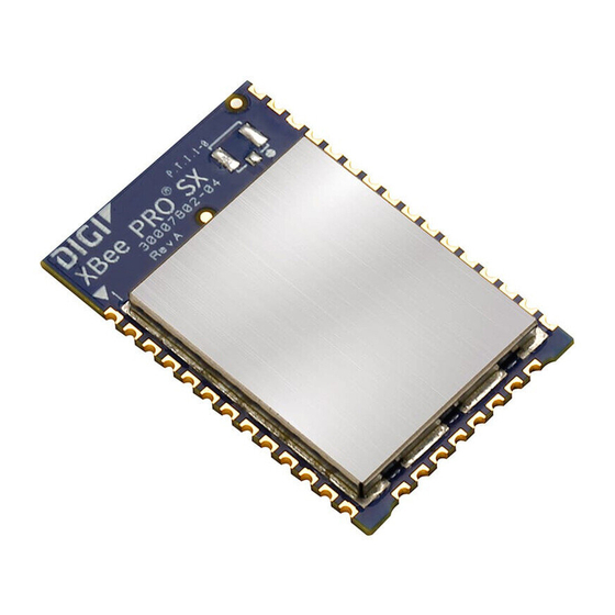
XBee®/XBee-PRO SX RF Module User Guide The XBee/XBee-PRO SX RF Module is an embedded radio frequency (RF) device that provides wireless connectivity to end-point devices in mesh networks. The XBee/XBee-PRO SX RF Module delivers up to 1 Watt of RF power and has excellent receive sensitivity, low operating current, and exceptional performance in low power modes. -
Page 12: Applicable Firmware And Hardware
This manual supports the following firmware: 0x900X USA and Canada, XBee/XBee-PRO SX 0x920x Australia, XBee/XBee-PRO SX 0x930X Brazil XBee/XBee-PRO SX 0x960X New Zealand, XBee SX only Note The New Zealand firmware only works with non-PRO hardware. v.10xx zigbee It supports the following hardware: XBee/XBee-PRO SX RF Module XBee®/XBee-PRO SX RF Module User Guide... -
Page 13: Technical Specifications
Technical specifications Regulatory conformity summary Power requirements Networking specifications Performance specifications General specifications GPIO specifications XBee®/XBee-PRO SX RF Module User Guide... -
Page 14: Regulatory Conformity Summary
ANATEL: 05774-16-01209 ANATEL: 05776-16-01209 Power requirements The following table describes the power requirements for the XBee/XBee-PRO SX RF Module. Specification Condition XBee SX value XBee-PRO SX value Supply voltage range 2.4 to 3.6 VDC 2.6 to 3.6 VDC Typical supply voltage 3.3 V... -
Page 15: Performance Specifications
Technical specifications Performance specifications Specification Value Optional 256-bit Advanced Encryption Standard (AES) cipher block chaining Encryption (CBC) Encryption. Use the EE command to enable encryption. Use the KY command to set the encryption key. Performance specifications The following table describes the performance specifications for the devices. XBee-PRO Specification Condition... -
Page 16: General Specifications
Technical specifications General specifications XBee-PRO Specification Condition XBee value value Receiver sensitivity Low data rate -113 dBm Middle data rate -106 dBm High data rate -103 dBm Receiver IF selectivity Low data rate ± 250 40 dB Low data rate ± 500 50 dB Middle data rate ±... -
Page 17: Gpio Specifications
Technical specifications GPIO specifications Specification Value Operating temperature -40 °C to 85 °C Digital I/O 13 I/O lines, 5 output lines Analog-to-digital converter (ADC) 4 10-bit analog inputs Pulse width modulator (PWM) 2 outputs GPIO specifications The following table provides the electrical specifications for the GPIO pads. GPIO electrical specification Value Voltage - supply... -
Page 18: Hardware
Hardware Mechanical drawings Pin signals XBee®/XBee-PRO SX RF Module User Guide... -
Page 19: Mechanical Drawings
Hardware Mechanical drawings Mechanical drawings The following figures show the XBee/XBee-PRO SX RF Module mechanical drawings. All dimensions are in centimeters. The XBee/XBee-PRO SX RF Module differs from other surface-mount XBee modules. It has an additional ground pad on the underside of the module used for heat dissipation. For more details, see PCB design and manufacturing. -
Page 20: Pin Signals
Hardware Pin signals Pin signals The following table describes the pin signals. Low-asserted signals are distinguished with a horizontal line over the signal name. Default Pin Name state Function Ground Power supply DIO13/DOUT I/O Output GPIO / UART data out DIN/DIO14/ I/O Input GPIO / UART data in... - Page 21 Hardware Pin signals Default Pin Name state Function DIO12 I/O Disabled GPIO RESET Drive low to reset device. Do not drive pin high; pin may only be driven open drain or low. Pin has an internal 20k pullup resistor DIO10/RSSI/PWM0 I/O Output GPIO / RX Signal Strength Indicator DIO11/PWM1 I/O Disabled GPIO / Pulse Width Modulator...
-
Page 22: Pin Connection Recommendations
Hardware Pin signals Default Pin Name state Function DIO7/CTS I/O Output GPIO / UART Clear to Send Flow Control DIO9/ON/SLEEP I/O Output GPIO / Module Sleep Status Indicator Feature not supported on this device. Used on other XBee devices for analog voltage reference. DIO5/ASSOC I/O Output GPIO / Associate Indicator... -
Page 23: Getting Started With The Xbee/Xbee-Pro Sx Rf Module Development
Brazil XK9X-DMS-1 This section describes how to set up an XBee network and adjust the XBee/XBee-PRO SX RF Module settings. XBee SX Development Board Connect XBee-PRO SX development boards to a PC Connect the XBIB-U-SS development board to a PC... -
Page 24: Xbee Sx Development Board
Getting started with the XBee/XBee-PRO SX RF Module Development Kit XBee SX Development Board XBee SX Development Board The following figure shows the XBee SX development board with onboard XBee-PRO SX RF pad module and the table that follows explains the callouts in the picture. Number Item Description RSSI LEDs... -
Page 25: Connect Xbee-Pro Sx Development Boards To A Pc
2. Connect the SX development boards to the USB port on a PC via the mini-USB cables. Separate the SX development boards by at least 2 m (6 ft). 3. Connect the antennas to the RPSMA connector on the SX development boards. The following table shows the XBee SX development kit contents. Description Quantity Part number... -
Page 26: Connect The Xbib-U-Ss Development Board To A Pc
Connect the XBIB-U-SS development board to a PC This step is optional. It shows how to set up the standalone XBee SX module on the XBIB-U-SS development board, which you can substitute as one of the range test devices or use with the other two devices to create a DigiMesh network. -
Page 27: Perform A Range Test
Getting started with the XBee/XBee-PRO SX RF Module Development Kit Perform a range test 3. Configure the following parameters: ID: 2015 NI: LOCAL_DEVICE AP: API Mode Without Escapes [1] 4. Click the Write radio settings button. 5. Select the other module and click the Default firmware settings button. 6. -
Page 28: Mesh Network Demonstration
8. Click Stop Range Test to stop the process at any time. Mesh network demonstration 1. Connect the two XBee PRO SX development boards and the XBIB-U-SS (with the XBee SX installed) to your computer. Open XCTU and find the three XBee devices. - Page 29 Getting started with the XBee/XBee-PRO SX RF Module Development Kit Mesh network demonstration To set up a DigiMesh network, you must first connect some XBee devices to a portable battery so you can move around with them. 1. Keep SENDER connected to the computer. 2.
- Page 30 Getting started with the XBee/XBee-PRO SX RF Module Development Kit Mesh network demonstration 6. Move RECEIVER away from SENDER until the Data Out LED does not blink anymore, meaning it has moved out of range. 7. Place BRIDGE about halfway between SENDER and RECEIVER and plug it in. BRIDGE joins the network, creates a bridge between the other two nodes, and relays messages from SENDER to RECEIVER.
-
Page 31: Modes
Modes Transparent and API operating modes Modes of operation XBee®/XBee-PRO SX RF Module User Guide... -
Page 32: Transparent And Api Operating Modes
Modes Transparent and API operating modes Transparent and API operating modes The firmware operates in several different modes. Two top-level modes establish how the device communicates with other devices through its serial interface: Transparent operating mode and API operating mode. Transparent operating mode Devices operate in this mode by default. -
Page 33: Modes Of Operation
Modes Modes of operation Feature Description Each API transmission Because acknowledgments are sent out of the serial interface, this can return a transmit provides more information about the health of the RF network and can status frame indicating be used to debug issues after the network has been deployed. the success or reason for failure Received data frames... -
Page 34: Transmit Mode
Modes Modes of operation Transmit mode When DigiMesh data is transmitted from one node to another, the destination node transmits a network-level acknowledgment back across the established route to the source node. This acknowledgment packet indicates to the source node that the destination node received the data packet. - Page 35 Modes Modes of operation string +++ (without Enter or Return) and another full second of silence, it knows to stop sending data through and start accepting commands locally. Note Do not press Return or Enter after typing +++ because it will interrupt the guard time silence and prevent you from entering Command mode.
- Page 36 Modes Modes of operation Apply command changes Any changes you make to the configuration command registers using AT commands do not take effect until you apply the changes. For example, if you send the BD command to change the baud rate, the actual baud rate does not change until you apply the changes.
-
Page 37: Sleep Modes
Sleep modes About sleep modes Normal mode Asynchronous pin sleep mode Asynchronous cyclic sleep mode Asynchronous cyclic sleep with pin wake up mode Synchronous sleep support mode Synchronous cyclic sleep mode The sleep timer Indirect messaging and polling Sleeping routers Sleep coordinator sleep modes in the DigiMesh network Synchronization messages Become a sleep coordinator... -
Page 38: About Sleep Modes
Sleep modes About sleep modes About sleep modes A number of low-power modes exist to enable devices to operate for extended periods of time on battery power. Use the SM command to enable these sleep modes. The sleep modes are characterized as either: Asynchronous (SM = 1, 4, 5). -
Page 39: Asynchronous Pin Sleep Mode
Sleep modes Asynchronous pin sleep mode Normal mode is the default sleep mode. If a device is in this mode, it does not sleep and is always awake. Use mains-power for devices in Normal mode. A device in Normal mode synchronizes to a sleeping network, but does not observe synchronization data routing rules;... -
Page 40: Synchronous Cyclic Sleep Mode
Sleep modes Synchronous cyclic sleep mode Note Because sleep support nodes do not sleep, they should be mains powered. Synchronous cyclic sleep mode Set SM to 8 to enter synchronous cyclic sleep mode. A device in synchronous cyclic sleep mode sleeps for a programmed time, wakes in unison with other nodes, exchanges data and sync messages, and then returns to sleep. -
Page 41: Polling
Sleep modes Sleeping routers poller for more than 2.5 times its SP value, then the packet is purged. We suggest setting the SP of the coordinator to the same value as the highest SP time that exists among the pollers in the network. -
Page 42: Synchronization Messages
Sleep modes Synchronization messages Synchronization messages A sleep coordinator regularly sends sync messages to keep the network in sync. Unsynchronized nodes also send messages requesting sync information. Sleep compatible nodes use Deployment mode when they first power up and the sync message has not been relayed. - Page 43 Sleep modes Synchronization messages XBee®/XBee-PRO SX RF Module User Guide...
-
Page 44: Become A Sleep Coordinator
Sleep modes Become a sleep coordinator Become a sleep coordinator In DigiMesh networks, a device can become a sleep coordinator in one of four ways: Define a preferred sleep coordinator A potential sleep coordinator misses three or more sync messages Press the Commissioning Pushbutton twice on a potential sleep coordinator Change the sleep timing values on a potential sleep coordinator Preferred sleep coordinator option... -
Page 45: Commissioning Pushbutton Option
Sleep modes Become a sleep coordinator It is possible for multiple nodes to declare themselves as the sleep coordinator. If this occurs, the firmware uses the following resolution criteria to identify the sleep coordinator from among the nodes using the selection process: 1. -
Page 46: Auto-Early Wake-Up Sleep Option
Sleep modes Select sleep parameters Auto-early wake-up sleep option If you have nodes that are missing sync messages and could be going out of sync with the rest of the network, enabling an early wake gives the device a better chance to hear the sync messages that are being broadcast. -
Page 47: Add A New Node To An Existing Network
Sleep modes Add a new node to an existing network 3. Power on the new nodes within range of the sleep coordinator. The nodes quickly receive a sync message and synchronize themselves to the short cycle SP and ST set on the sleep coordinator. -
Page 48: Change Sleep Parameters
Sleep modes Change sleep parameters If you do not use one of these two methods, you must wait for the network to wake up before adding the new node. Place the new node in range of the network with a sleep/wake cycle that is shorter than the wake period of the network. -
Page 49: Diagnostics
Sleep modes Diagnostics intervals. When this occurs the first task is to repair, replace, and strengthen the weak link with new and/or redundant devices to fix the problem and prevent it from occurring in the future. When you use the default DigiMesh sleep parameters, separated subnets do not drift out of phase with each other. -
Page 50: Missed Sync Messages Command
Sleep modes Diagnostics Missed sync messages command Use the MS command to query the number of cycles that elapsed since the device received a sync message. Sleep status API messages When you use the SO command to enable this option, a device that is in API operating mode outputs modem status frames immediately after it wakes up and prior to going to sleep. -
Page 51: Networking Methods
Networking methods The MAC and PHY layers 64-bit addresses Make a unicast transmission Make a broadcast transmission Delivery methods XBee®/XBee-PRO SX RF Module User Guide... -
Page 52: The Mac And Phy Layers
Networking methods The MAC and PHY layers The MAC and PHY layers Most network protocols use the concept of layers to separate different components and functions into independent modules that developers can assemble in different ways. The PHY layer defines the physical and electrical characteristics of the network. It is responsible for managing the hardware that modulates and demodulates the RF bits. -
Page 53: Make A Unicast Transmission
Make a unicast transmission Use the SH and SL commands to read this address. The form of the address is: 0x0013A2XXXXXXXXXX. The first six digits are the Digi Organizationally Unique Identifier (OUI). The broadcast address is 0x000000000000FFFF. Make a unicast transmission To transmit to a specific device in Transparent operating mode: Set DH:DL to the SH:SL of the destination device. -
Page 54: Repeater/Directed Broadcast
Networking methods Delivery methods Repeater/directed broadcast All of the routers in a network receive and repeat directed broadcast transmissions. Because it does not use ACKs, the originating node sends the broadcast multiple times. By default a broadcast transmission is sent four times—the extra transmissions become automatic retries without acknowledgments. - Page 55 Networking methods Delivery methods Reliable delivery. Reliable delivery of data is accomplished by means of acknowledgments. Sleep modes. Low power sleep modes with synchronized wake are supported with variable sleep and wake times. With mesh networking, the distance between two nodes does not matter as long as there are enough nodes in between to pass the message along.
- Page 56 Networking methods Delivery methods Packet tracking prevents a node from resending a broadcast message more than MT+1 times. This means that a node that relays a broadcast will only relay it after it receives it the first time and it will discard repeated instances of the same packet.
- Page 57 Networking methods Delivery methods The maximum delay occurs when the sender and receiver are on the opposite ends of the network. The NH and %H parameters define the maximum broadcast delay as follows: BroadcastTxTime = NH * NN * %8 Unless BH <...
-
Page 58: Serial Communication
Serial communication UART data flow SPI signals Slave mode characteristics Full duplex operation Low power operation Configuration considerations SPI and API mode SPI parameters Serial port selection UART flow control XBee®/XBee-PRO SX RF Module User Guide... -
Page 59: Uart Data Flow
Serial communication UART data flow UART data flow Devices that have a UART interface connect directly to the pins of the XBee/XBee-PRO SX RF Module as shown in the following figure. The figure shows system data flow in a UART-interfaced environment. -
Page 60: Signal Description
Serial communication Slave mode characteristics Signal Pin number Applicable AT command SPI_SCLK (Serial clock) SPI_SSEL (Slave select) SPI_ATTN (Attention) By default, the inputs have pull-up resistors enabled. Use the PR command to disable the pull-up resistors. When the SPI pins are not connected but the pins are configured for SPI operation, then the device requires the pull-ups for proper UART operation. -
Page 61: Full Duplex Operation
The following figure illustrates the SPI interface while valid data is being sent in both directions. Low power operation Sleep modes generally work the same on SPI as they do on UART. By default, Digi configures DIO8 (SLEEP_REQUEST) as a peripheral and during pin sleep it wakes the device and puts it to sleep. This applies to both the UART and SPI serial interfaces. -
Page 62: Configuration Considerations
Serial communication Configuration considerations It has the disadvantage of putting the device to sleep whenever the SPI master negates SPI_SSEL (meaning time is lost waiting for the device to wake), even if that was not the intent. If the user has full control of SPI_SSEL so that it can control pin sleep, whether or not data needs to be transmitted, then sharing the pin may be a good option in order to make the SLEEP_REQUEST pin available for another purpose. -
Page 63: Serial Receive Buffer
Serial communication UART flow control If both ports are disabled on reset, the device uses the UART in spite of the wrong configuration so that at least one serial port is operational. Serial receive buffer When serial data enters the device through the DIN pin (or the MOSI pin), it stores the data in the serial receive buffer until the device can process it. -
Page 64: At Commands
AT commands Special commands MAC/PHY commands Diagnostic commands - MAC statistics and timeouts Network commands Addressing commands Diagnostic - addressing commands Addressing discovery/configuration commands Security commands Serial interfacing commands I/O settings commands I/O sampling commands I/O line passing commands Sleep commands Diagnostic - sleep status/timing commands Command mode options Firmware version/information commands... -
Page 65: Special Commands
AT commands Special commands Special commands The following commands are special commands. AC (Apply Changes) Immediately applies new settings without exiting Command mode. Parameter range Default FR (Software Reset) Resets the device. The device responds immediately with an OK and performs a reset 100 ms later. If you issue FR while the device is in Command Mode, the reset effectively exits Command mode. -
Page 66: Mac/Phy Commands
AT commands MAC/PHY commands MAC/PHY commands The following AT commands are MAC/PHY commands. AF (Available Frequencies) You can query this read-only command to return a bitfield of the frequencies that are available in the device’s region of operation. This command returns a bitfield. Each bit corresponds to a physical channel. -
Page 67: Mf (Minimum Frequencies)
AT commands MAC/PHY commands separate channels or to use different HP (Preamble ID) and/or ID (Network IDs) to avoid receiving data from the other network. You may find the ED (Energy Detect) command useful when choosing what channels to enable or disable. -
Page 68: Hp (Preamble Id)
AT commands MAC/PHY commands HP (Preamble ID) The preamble ID for which the device communicates. Only devices with matching preamble IDs can communicate with each other. Different preamble IDs minimize interference between multiple sets of devices operating in the same vicinity. When receiving a packet, the device checks this before the network ID, as it is encoded in the preamble, and the network ID is encoded in the MAC header. -
Page 69: Pl (Tx Power Level)
AT commands MAC/PHY commands Parameter RF data rate Receiver sensitivity 10 kb/s -113 dBm 110 kb/s -106 dBm 250 kb/s -103 dBm Default PL (TX Power Level) Sets or displays the power level at which the device transmits conducted power. For XBee, PL = 4, PM = 1 is tested at the time of manufacturing. -
Page 70: Rr (Unicast Mac Retries)
AT commands Diagnostic commands - MAC statistics and timeouts Default RR (Unicast Mac Retries) Set or read the maximum number of MAC level packet delivery attempts for unicasts. If RR is non- zero, the sent unicast packets request an acknowledgment from the recipient. Unicast packets can be retransmitted up to RR times if the transmitting device does not receive a successful acknowledgment. -
Page 71: Er (Receive Count Error)
AT commands Diagnostic commands - MAC statistics and timeouts ER (Receive Count Error) This count increments when a device receives a packet that contains integrity errors of some sort. When the number reaches 0xFFFF, the firmware does not count further events. To reset the counter to any 16-bit value, append a hexadecimal parameter to the command. -
Page 72: H (Mac Unicast One Hop Time)
AT commands Network commands Parameter range 0 - 0xFFFF Default %H (MAC Unicast One Hop Time) The MAC unicast one hop time timeout in milliseconds. If you change the MAC parameters it can change this value. Parameter range [read-only] Default %8 (MAC Broadcast One Hop Time) The MAC broadcast one hop time timeout in milliseconds. -
Page 73: Bh (Broadcast Hops)
AT commands Network commands Parameter Description Routes packets Indirect message coordinator Non-routing device Non-routing coordinator Indirect message poller Non-routing poller Default BH (Broadcast Hops) The maximum transmission hops for broadcast data transmissions. This will not affect Point-to- Multipoint transmissions (TO = 40). If you set BH greater than NH, the device uses the value of NH. -
Page 74: Nn (Network Delay Slots)
AT commands Addressing commands Default NN (Network Delay Slots) Set or read the maximum random number of network delay slots before rebroadcasting a network packet. Parameter range 1 - 0x5 network delay slots Default Addressing commands The following AT commands are addressing commands. SH (Serial Number High) Displays the upper 32 bits of the unique IEEE 64-bit extended address assigned to the XBee in the factory. -
Page 75: Dl Command
AT commands Addressing commands Parameter range 0 - 0xFFFFFFFF Default DL command Set or display the upper 32 bits of the 64-bit destination address. When you combine DH with DL, it defines the destination address that the device uses for transmissions in Transparent mode. The destination address is also used for I/O sampling in both Transparent and API modes. -
Page 76: Ni (Node Identifier)
AT commands Addressing commands When you set BR to 0 the TO option has the DigiMesh and Repeater mode disabled automatically. Default 0xC0 NI (Node Identifier) Stores the node identifier string for a device, which is a user-defined name or description of the device. -
Page 77: Ci (Cluster Id)
AT commands Diagnostic - addressing commands Bit field Option Description Append the DD (Digi Device Identifier) value to ND responses or API node identification 0x01 frames. Local device sends ND response frame out the serial interface when ND is issued. -
Page 78: Addressing Discovery/Configuration Commands
AT commands Addressing discovery/configuration commands Addressing discovery/configuration commands AG (Aggregator Support) The AG command sends a broadcast through the network that has the following effects on nodes that receive the broadcast: The receiving node establishes a DigiMesh route back to the originating node, if there is space in the routing table. -
Page 79: Nd (Network Discover)
STATUS<CR> (1 Byte: Reserved) PROFILE_ID<CR> (2 Bytes) MANUFACTURER_ID<CR> (2 Bytes) DIGI DEVICE TYPE<CR> (4 Bytes. Optionally included based on NO settings.) RSSI OF LAST HOP<CR> (1 Byte. Optionally included based on NO settings.) <CR> After (NT * 100) milliseconds, the command ends by returning a <CR>. -
Page 80: Security Commands
STATUS<CR> (1 Byte: Reserved) PROFILE_ID<CR> (2 Bytes) MANUFACTURER_ID<CR> (2 Bytes) DIGI DEVICE TYPE<CR> (4 Bytes. Optionally included based on NO settings.) RSSI OF LAST HOP<CR> (1 Byte. Optionally included based on NO settings.) <CR> If you send the FN command in Command mode, after (NT*100) ms + overhead time, the command ends by returning a carriage return, represented by <CR>. -
Page 81: Serial Interfacing Commands
AT commands Serial interfacing commands Parameter range 256-bit value (64 Hexadecimal digits) Default Serial interfacing commands The following AT commands are serial interfacing commands. BD (Interface Data Rate) Sets and reads the serial interface data rate (baud rate) between the device and the host. The baud rate is the rate that the host sends serial data to the device. -
Page 82: Nb (Parity)
AT commands Serial interfacing commands Parameter Configuration (b/s) 1200 2400 4800 9600 19200 38400 57600 115200 230400 460800 921600 Default NB (Parity) Set or read the serial parity settings for UART communications. Parameter range 0x00 - 0x02 Parameter Description 0x00 No parity 0x01 Even parity... -
Page 83: Ro (Packetization Timeout)
AT commands Serial interfacing commands Parameter Configuration 0x00 One stop bit 0x01 Two stop bits Default 0x00 RO (Packetization Timeout) Set or read the number of character times of inter-character silence required before transmission begins when operating in Transparent mode. Set RO to 0 to transmit characters as they arrive instead of buffering them into one RF packet. -
Page 84: Ao (Api Options)
AT commands I/O settings commands Parameter Description API Mode Without Escapes. The device packetizes all UART input and output data in API format, without escape sequences. API Mode With Escapes. The device is in API mode and inserts escaped sequences to allow for control characters. -
Page 85: D1 (Dio1/Ad1)
AT commands I/O settings commands Parameter Description Disabled Unmonitored digital input Commissioning Pushbutton Digital input Digital output, low Digital output, high Default D1 (DIO1/AD1) Sets or displays the DIO1/AD1 configuration (pin 32). Parameter range 0, 2 - 5 Parameter Description Disabled Digital input Digital output, low... -
Page 86: D3 (Dio3/Ad3)
AT commands I/O settings commands Parameter Description Disabled Digital input Digital output, low Digital output, high Default D3 (DIO3/AD3) Sets or displays the DIO3/AD3 configuration (pin 30). Parameter range 0, 2 - 5 Parameter Description Disabled Unmonitored digital input Digital input Digital output, low Digital output, high Default... -
Page 87: D5 (Dio5/Associated_Indicator)
AT commands I/O settings commands Parameter Description Unmonitored digital input Digital input Digital output, low Digital output, high Default D5 (DIO5/ASSOCIATED_INDICATOR) Sets or displays the DIO5/ASSOCIATED_INDICATOR configuration (pin 28). Parameter range 0, 1, 3 - 5 Parameter Description Disabled Associate LED indicator - blinks when associated Digital input Digital output, default low Digital output, default high... -
Page 88: D7 (Dio7/Cts)
AT commands I/O settings commands Parameter Description Digital input Digital output, low Digital output, high Default D7 (DIO7/CTS) Sets or displays the DIO7/CTS configuration (pin 25). Parameter range 0, 1, 3 - 7 Parameter Description Disabled CTS flow control Digital input Digital output, low Digital output, high RS-485 Tx enable, low Tx (0 V on transmit, high when idle) -
Page 89: D9 (Dio9/On_Sleep)
AT commands I/O settings commands Parameter Description Disabled Digital input Digital output, low Digital output, high Default D9 (DIO9/ON_SLEEP) Sets or displays the DIO9/ON_SLEEP configuration (pin 26). Parameter range 0, 1, 3 - 5 Parameter Description Disabled ON/SLEEP output Digital input Digital output, low Digital output, high Default... -
Page 90: P1 (Dio11/Pwm1 Configuration)
AT commands I/O settings commands Parameter Description RSSI PWM0 output PWM0 output Digital input Digital output, low Digital output, high Default P1 (DIO11/PWM1 Configuration) Sets or displays the DIO11/PWM1 configuration (pin 8). When configured as a PWM1 output, you can use M1 to set the PWM duty cycle. Parameter range 0 - 5 0 - 6... -
Page 91: P3 (Dio13/Dout)
AT commands I/O settings commands Parameter Description Digital input Digital output, low Digital output, high RX LED Default P3 (DIO13/DOUT) Sets or displays the DIO13/DOUT configuration (pin 3). Parameter range 0, 1 Parameter Description Disabled UART DOUT enabled Default P4 (DIO14/DIN) Sets or displays the DIO14/DIN/CONFIG configuration (pin 4). -
Page 92: P6 (Spi_Mosi Configuration)
AT commands I/O settings commands Default P5 (DIO15/SPI_MISO) Sets or displays the DIO15/SPI_MISO configuration (pin 17). Parameter range 0, 1 0, 1, 4, 5 Parameter Description Disabled SPI_MISO Digital output low Digital output high Default P6 (SPI_MOSI Configuration) Sets or displays the DIO16/SPI_MOSI configuration (pin 16). Parameter range 1, 2, 4, 5 Parameter... -
Page 93: P9 (Dio19/Spi_Attn)
AT commands I/O settings commands P7 (DIO17/SPI_SSEL ) Sets or displays the DIO17/SPI_SSEL configuration (pin 15). Parameter range 1, 2 1, 2, 4, 5 Parameter Description Disabled SPI_SSEL Digital output low Digital output, high Default P8 (DIO18/SPI_SCLK) Sets or displays the DIO18/SPI_SCLK configuration (pin 14). Parameter range 1, 2, 4, 5 Parameter... -
Page 94: Pd (Pull Direction)
AT commands I/O settings commands Parameter range 1, 2, 4 - 6 Parameter Description Disabled SPI_ATTN Digital output low Digital output high UART data present indicator Default PD (Pull Direction) The resistor pull direction bit field (1 = pull-up, 0 = pull-down) for corresponding I/O lines that are set by the PR command. -
Page 95: M0 (Pwm0 Duty Cycle)
AT commands I/O settings commands I/O line Module pin DIO6/RTS DIO8/SLEEP_REQUEST DIO14/DIN/CONFIG DIO5/ASSOCIATE DIO9/On/SLEEP DIO12 DIO10/RSSI/PWM0 DIO11/PWM1 DIO7/CTS DIO13/DOUT DIO15/SPI_MISO DIO16/SPI_MOSI DIO17/SPI_ SSEL DIO18/SPI_SCLK DIO19/SPI_ATTN Parameter range 0 - 0xFFFFF (bit field) Default 0xFFFFF M0 (PWM0 Duty Cycle) The duty cycle of the PWM0 line (pin 7). Use the P0 command to configure the line as a PWM output. -
Page 96: Lt (Associate Led Blink Time)
AT commands I/O sampling commands Default LT (Associate LED Blink Time) Set or read the Associate LED blink time. If you use the D5 command to enable the Associate LED functionality (DIO5/Associate pin), this value determines the on and off blink times for the LED when the device has joined the network. -
Page 97: Ic (Dio Change Detect)
AT commands I/O sampling commands IC (DIO Change Detect) Set or read the digital I/O pins to monitor for changes in the I/O state. IC works with the individual pin configuration commands (D0 - D9, P0 - P2). If you enable a pin as a digital I/O, use the IC command to force an immediate I/O sample transmission when the DIO state changes. -
Page 98: Ir (Sample Rate)
AT commands I/O line passing commands Default IR (Sample Rate) Set or read the I/O sample rate to enable periodic sampling. When set, this parameter causes the device to sample all enabled DIO and ADC at a specified interval. If you set the I/O sample rate to greater than 0, the device samples and transmits all enabled digital I/O and analog inputs every IR milliseconds. -
Page 99: Iu (I/O Output Enable)
AT commands I/O line passing commands You can perform Digital Line Passing on any of the Digital I/O lines. Digital Inputs directly map to Digital Outputs of each digital pin. Analog Line Passing can be performed only on the first two ADC lines: ADC0 corresponds with PWM0 ADC1 corresponds with PWM1 IU (I/O Output Enable) -
Page 100: T2 (D2 Output Timeout)
AT commands I/O line passing commands Parameter range 0 - 0x1770 (x 100 ms) Default T2 (D2 Output Timeout) Specifies how long pin D2 holds a given value before it reverts to configured value. If set to 0, there is no timeout. -
Page 101: T6 (D6 Output Timeout)
AT commands I/O line passing commands T6 (D6 Output Timeout) Specifies how long pin D6 holds a given value before it reverts to configured value. If set to 0, there is no timeout. Parameter range 0 - 0x1770 (x 100 ms) Default T7 (D7 Output Timeout) Specifies how long pin D7 holds a given value before it reverts to configured value. -
Page 102: Q1 (P1 Timeout)
AT commands I/O line passing commands Default Q1 (P1 Timeout) Specifies how long pin P1 holds a given value before it reverts to configured value. If set to 0, there is no timeout. Parameter range 0 - 0x1770 (x 100 ms) Default Q2 (P2 Timeout) Specifies how long pin P2 holds a given value before it reverts to configured value. -
Page 103: Sleep Commands
AT commands Sleep commands output. Parameter range 0 - 0x1770 (x 100 ms) Default 0xFF Sleep commands The following commands are sleep commands. SM (Sleep Mode) Sets or displays the sleep mode of the device. Normal mode is always awake. Pin sleep modes allow you to wake the device with the SLEEP_ REQUEST line. -
Page 104: So (Sleep Options)
AT commands Sleep commands Parameter Description Asynchronous Cyclic Sleep Pin Wake. When you assert the SLEEP_RQ pin, the device enters a cyclic sleep mode similar to Asynchronous Cyclic Sleep. When you de-assert the SLEEP_RQ pin, the device immediately wakes up. The device does not sleep when you de-assert the SLEEP_RQ pin. -
Page 105: Sp (Sleep Time)
AT commands Sleep commands Cyclic Sleep. This allows external circuitry to sleep longer than the SP time. During cycles when ON_SLEEP is de-asserted, the device wakes up and checks for any serial or RF data. If it receives any such data, then it asserts the ON_SLEEP line and the device wakes up fully. Otherwise, the device returns to sleep after checking. -
Page 106: Diagnostic - Sleep Status/Timing Commands
AT commands Diagnostic - sleep status/timing commands If you set WH to a non-zero value, this timer specifies a time in milliseconds that the device delays after waking from sleep before sending data out the UART or transmitting an I/O sample. If the device receives serial characters, the WH timer stops immediately. -
Page 107: Os (Operating Sleep Time)
AT commands Command mode options OS (Operating Sleep Time) Reads the current network sleep time that the device is synchronized to, in units of 10 milliseconds. If the device has not been synchronized, then OS returns the value of SP. If the device synchronizes with a sleeping router network, OS may differ from SP. -
Page 108: Cc (Command Character)
AT commands Firmware version/information commands CC (Command Character) The character value the device uses to enter Command mode. The default value (0x2B) is the ASCII code for the plus (+) character. You must enter it three times within the guard time to enter Command mode. To enter Command mode, there is also a required period of silence before and after the command sequence characters of the Command mode sequence (GT + CC + GT). -
Page 109: Hv (Hardware Version)
Parameter range 0 - 0xFFFF [read-only] Default 0x0A00 - set in the firmware DD (Device Type Identifier) Stores the Digi device type identifier value. Use this value to differentiate between multiple XBee devices. Parameter range 0 - 0xFFFFFFFF [read-only] Default... - Page 110 AT commands Firmware version/information commands Parameter range Default XBee®/XBee-PRO SX RF Module User Guide...
-
Page 111: Operate In Api Mode
Operate in API mode API mode overview Use the AP command to set the operation mode API frame format API frames XBee®/XBee-PRO SX RF Module User Guide... -
Page 112: Api Mode Overview
Operate in API mode API mode overview API mode overview By default, the XBee/XBee-PRO SX RF Module acts as a serial line replacement (Transparent operation), it queues all UART data that it receive through the DI pin for RF transmission. When the device receives an RF packet, it sends the data out the DO pin with no additional information. -
Page 113: Api Operation With Escaped Characters (Ap Parameter = 2)
API mode, see the Escaped Characters and API Mode 2 in the Digi Knowledge base. API escaped operating mode works similarly to API mode. The only difference is that when working in API escaped mode, the software must escape any payload bytes that match API frame specific data, such as the start-of-frame byte (0x7E). -
Page 114: Length Field
Operate in API mode API frame format In API mode with escaped characters, the length field does not include any escape characters in the frame and the firmware calculates the checksum with non-escaped data. Example: escape an API frame To express the following API non-escaped frame in API operating mode with escaped characters: Frame Data Start delimiter Length Frame type Checksum... -
Page 115: Api Frames
Operate in API mode API frames 1. Add all bytes of the packet, except the start delimiter 0x7E and the length (the second and third bytes). 2. Keep only the lowest 8 bits from the result. 3. Subtract this quantity from 0xFF. To verify the checksum of an API frame: 1. -
Page 116: Api Frame Exchanges
Operate in API mode API frames API frame exchanges Every outgoing API frame has a corresponding response (or ACK) frame that indicates the success or failure of the outgoing API frame. This section details some of the common API exchanges that occur. You can use the Frame ID field to correlate between the outgoing frames and associated responses. - Page 117 Operate in API mode API frames Remote AT commands The following image shows the API frame exchanges that take place on the serial interface when you send a 0x17 Remote AT Command frame The 0x97 Remote AT Command Response is always generated and you can use it to identify if the remote device successfully received and applied the command.
-
Page 118: Code To Support Future Api Frames
Operate in API mode API frames Code to support future API frames If your software application supports the API, you should make provisions that allow for new API frames in future firmware releases. For example, you can include the following section of code on a host microprocessor that handles serial API frames that are sent out the device's DOUT pin: void XBee_HandleRxAPIFrame(_apiFrameUnion *papiFrame){ switch(papiFrame->api_id){... -
Page 119: Legacy Tx Request Frame - 0X00
Description This frame causes the device to send payload data as an RF packet. This packet format is deprecated and should only be used by customers who require compatibility with legacy Digi RF products. We encourage you to use Transmit Request frame - 0x10 to initiate API transmissions. - Page 120 Operate in API mode API frames Frame data fields Offset Example Destination address MSB 5 0x00 0x13 0xA2 0x00 0x40 0x52 0xC5 LSB 12 0x07 Options 0x00 RF data 0x54 0x78 0x44 0x61 0x74 0x61 Checksum 0xA5 XBee®/XBee-PRO SX RF Module User Guide...
-
Page 121: At Command Frame - 0X08
Operate in API mode API frames AT Command Frame - 0x08 Description Use this frame to query or set device parameters on the local device. This API command applies changes after running the command. You can query parameter values by sending the 0x08 AT Command frame with no parameter value field (the two-byte AT command is immediately followed by the frame checksum). -
Page 122: At Command - Queue Parameter Value Frame - 0X09
Operate in API mode API frames AT Command - Queue Parameter Value frame - 0x09 Description This frame allows you to query or set device parameters. In contrast to the AT Command (0x08) frame, this frame queues new parameter values and does not apply them until you issue either: The AT Command (0x08) frame (for API type) The AC command When querying parameter values, the 0x09 frame behaves identically to the 0x08 frame. - Page 123 Operate in API mode API frames Frame data fields Offset Example AT command 0x42 (B) 0x44 (D) Parameter value (BD7 = 115200 baud) 0x07 Checksum 0x68 XBee®/XBee-PRO SX RF Module User Guide...
-
Page 124: Transmit Request Frame - 0X10
Operate in API mode API frames Transmit Request frame - 0x10 Description This frame causes the device to send payload data as an RF packet to a specific destination. For broadcast transmissions, set the 64-bit destination address to 0x000000000000FFFF . For unicast transmissions, set the 64 bit address field to the address of the desired destination node. - Page 125 Operate in API mode API frames Frame data fields Offset Example Start delimiter 0x7E Length MSB 1 0x00 LSB 2 0x16 Frame type 0x10 Frame ID 0x01 64-bit destination MSB 5 0x00 address 0x13 0xA2 0x00 0x40 0x0A 0x01 LSB 12 0x27 16-bit destination 0xFF...
-
Page 126: Explicit Addressing Command Frame - 0X11
Operate in API mode API frames Explicit Addressing Command frame - 0x11 Description This frame is similar to Transmit Request (0x10), but it also requires you to specify the application- layer addressing fields: endpoints, cluster ID, and profile ID. This frame causes the device to send payload data as an RF packet to a specific destination, using specific source and destination endpoints, cluster ID, and profile ID. - Page 127 Operate in API mode API frames 64-bit address: 0x0013A200 01238400 Source endpoint: 0xE8 Destination endpoint: 0xE8 Cluster ID: 0x11 Profile ID: 0xC105 Payload: TxData Frame data fields Offset Example Start delimiter 0x7E Length MSB 1 0x00 LSB 2 0x1A Frame type 0x11 Frame ID 0x01...
- Page 128 Operate in API mode API frames Frame data fields Offset Example Data payload 0x54 0x78 0x44 0x61 0x74 0x61 Checksum 0xA6 XBee®/XBee-PRO SX RF Module User Guide...
-
Page 129: Remote At Command Request Frame - 0X17
Operate in API mode API frames Remote AT Command Request frame - 0x17 Description Used to query or set device parameters on a remote device. For parameter changes on the remote device to take effect, you must apply changes, either by setting the Apply Changes options bit, or by sending an AC command to the remote. - Page 130 Operate in API mode API frames Frame data fields Offset Example Start delimiter 0x7E Length MSB 1 0x00 LSB 2 0x10 0x17 Frame type Frame ID 0x01 64-bit destination address MSB 5 0x00 0x13 0xA2 0x00 0x40 0x40 0x11 LSB 12 0x22 Reserved 0xFF...
-
Page 131: Modem Status Frame - 0X8A
Operate in API mode API frames Modem Status frame - 0x8A Description Devices send the status messages in this frame in response to specific conditions. Format The following table provides the contents of the frame. For details on frame structure, see API frame specifications. -
Page 132: Transmit Status Frame - 0X8B
Operate in API mode API frames Transmit Status frame - 0x8B Description When a Transmit Request (0x10, 0x11) completes, the device sends a Transmit Status message out of the serial interface. This message indicates if the Transmit Request was successful or if it failed. Format The following table provides the contents of the frame. - Page 133 Operate in API mode API frames Frame Fields Offset Example Frame ID 0x47 Reserved 0xFF 0xFE Transmit retry count 0x00 Delivery status 0x00 Discovery status 0x02 Checksum 0x2E XBee®/XBee-PRO SX RF Module User Guide...
-
Page 134: Route Information Packet Frame - 0X8D
Operate in API mode API frames Route Information Packet frame - 0x8D Description If you enable NACK or the Trace Route option on a DigiMesh unicast transmission, a device can output this frame for the transmission. Format The following table provides the contents of the frame. For details on frame structure, see API frame specifications. - Page 135 Operate in API mode API frames Frame data fields Offset Example Start delimiter 0x7E Length MSB 1 0x00 LSB 2 0x2A Frame type 0x8D Source event 0x12 Length 0x27 Timestamp MSB 6 0x9C 0x93 0x81 LSB 9 0x7F ACK timeout count 0x00 TX blocked count 0x00...
- Page 136 Operate in API mode API frames Frame data fields Offset Example Responder address MSB 29 0x00 0x13 0xA2 0x00 0x40 0x52 0xBB LSB 36 0xBB Receiver address MSB 37 0x00 0x13 0xA2 0x00 0x40 0x52 0xCC LSB 44 0xCC Checksum 0xD2 XBee®/XBee-PRO SX RF Module User Guide...
-
Page 137: Aggregate Addressing Update Frame - 0X8E
Operate in API mode API frames Aggregate Addressing Update frame - 0x8E Description The device sends out an Aggregate Addressing Update frame on the serial interface of an API-enabled node when an address update frame (generated by the AG command being issued on a node in the network) causes the node to update its DH and DL registers. - Page 138 Operate in API mode API frames Frame data fields Offset Example New address MSB 5 0x00 0x13 0xA2 0x00 0x40 0x52 0xBB LSB 12 0xBB Old address 0x00 0x13 0xA2 0x00 0x40 0x52 0xAA 0xAA Checksum 0x19 XBee®/XBee-PRO SX RF Module User Guide...
-
Page 139: Legacy Rx Indicator Frame - 0X80
Operate in API mode API frames Legacy RX Indicator frame - 0x80 Description When a device in Legacy Packet Mode (AO = 2) receives an RF data packet, it sends this frame out the serial interface. Format The following table provides the contents of the frame. For details on frame structure, see API frame specifications. - Page 140 Operate in API mode API frames Frame data fields Offset Example Length MSB 1 0x00 LSB 2 0x11 Frame type 0x80 64-bit source address MSB 4 0x00 0x13 0xA2 0x00 0x40 0x52 0xC5 LSB 11 0x07 RSSI 0x28 Options 0x01 0x52 Received data 0x78...
-
Page 141: At Command Response Frame - 0X88
Operate in API mode API frames AT Command Response frame - 0x88 Description A device sends this frame in response to an AT Command (0x08 or 0x09) frame. Some commands send back multiple frames; for example, the ND command. Format The following table provides the contents of the frame. - Page 142 Operate in API mode API frames Frame data fields Offset Example Command data Checksum 0xF0 XBee®/XBee-PRO SX RF Module User Guide...
-
Page 143: Legacy Tx Status Frame - 0X89
Operate in API mode API frames Legacy TX Status frame - 0x89 Description When a Legacy TX Request (0x00) is complete, the device sends a Legacy TX Status frame. This message indicates if the packet transmitted successfully or if there was a failure. Format The following table provides the contents of the frame. -
Page 144: Rx Indicator Frame - 0X90
Operate in API mode API frames RX Indicator frame - 0x90 Description When a device configured with a standard API Rx Indicator (AO = 0) receives an RF data packet, it sends it out the serial interface using this message type. Format The following table provides the contents of the frame. - Page 145 Operate in API mode API frames Frame data fields Offset Example MSB 4 0x00 64-bit source address 0x13 0xA2 0x00 0x40 0x52 0x2B LSB 11 0xAA Reserved 0xFF 0xFE Receive options 0x01 Received data 0x52 0x78 0x44 0x61 0x74 0x61 Checksum 0x11 XBee®/XBee-PRO SX RF Module User Guide...
-
Page 146: Explicit Rx Indicator Frame - 0X91
Operate in API mode API frames Explicit Rx Indicator frame - 0x91 Description When a device configured with explicit API Rx Indicator (AO = 1) receives an RF packet, it sends it out the serial interface using this message type. Format The following table provides the contents of the frame. - Page 147 Operate in API mode API frames Frame data fields Offset Example Frame type 0x91 64-bit source address MSB 4 0x00 0x13 0xA2 0x00 0x40 0x52 0x2B LSB 11 0xAA Reserved 0xFF 0xFE Source endpoint 0xE0 Destination endpoint 0xE0 Cluster ID 0x22 0x11 Profile ID...
-
Page 148: Node Identification Indicator Frame - 0X95
NO (Network Discovery Options). Source event 1=Frame sent by node identification pushbutton event. Digi Profile ID 31-32 Set to the Digi application profile ID. Digi 33-34 Set to the Digi Manufacturer ID. Manufacturer Digi DD value Reports the DD value of the responding device. Use the NO command to... - Page 149 Operate in API mode API frames Example If you press the commissioning pushbutton on a remote device with 64-bit address 0x0013A200407402AC and a default NI string sends a Node Identification, all devices on the network receive the following node identification indicator: A remote device with 64-bit address 0x0013A200407402AC and a default NI string sends a Node Identification, all devices on the network receive the following node identification indicator: If you press the commissioning button on a remote router device with 64-bit address 0x0013A200...
- Page 150 0x74 0x02 0xAC LSB 24 NI string 0x20 0x00 Reserved 0xFF 0xFE Device type 0x01 Source event 0x01 Digi Profile ID 0xC1 0x05 Digi Manufacturer ID 0x10 0x1E Digi DD value 0x00 (optional) 0x0C 0x00 0x00 RSSI (optional) 0x2E Checksum 0x33 XBee®/XBee-PRO SX RF Module User Guide...
-
Page 151: Remote Command Response Frame - 0X97
Operate in API mode API frames Remote Command Response frame - 0x97 Description If a device receives this frame in response to a Remote Command Request (0x17) frame, the device sends an AT Command Response (0x97) frame out the serial interface. Some commands, such as the ND command, may send back multiple frames. - Page 152 Operate in API mode API frames Frame data fields Offset Example 64-bit source (remote) address MSB 5 0x00 0x13 0xA2 0x00 0x40 0x52 0x2B LSB 12 0xAA Reserved 0xFF 0xFE 16-bit source (remote) address MSB 13 0x7D LSB 14 0x84 AT commands 0x53 (S) 0x4C (L)
-
Page 153: Work With Networked Devices
Work with networked devices Network commissioning and diagnostics Local configuration Remote configuration Establish and maintain network links Test links in a network - loopback cluster Test links between adjacent devices XBee®/XBee-PRO SX RF Module User Guide... -
Page 154: Network Commissioning And Diagnostics
Work with networked devices Network commissioning and diagnostics Network commissioning and diagnostics We call the process of discovering and configuring devices in a network for operation, "network commissioning." Devices include several device discovery and configuration features. In addition to configuring devices, you must develop a strategy to place devices to ensure reliable routes. To accommodate these requirements, modules include features to aid in placing devices, configuring devices, and network diagnostics. -
Page 155: Establish And Maintain Network Links
Work with networked devices Establish and maintain network links 1. The status of the command, which is either success or the reason for failure. 2. In the case of a command query, it includes the register value. The device that sends a remote command does not receive a remote command response frame if: 1. -
Page 156: Replace Nodes
Work with networked devices Test links in a network - loopback cluster Example two: If you want all of the nodes in the network to build routes to an aggregator node with a MAC address of 0x0013A200 4052C507 without affecting the DH and DL registers of any nodes in the network: 1. -
Page 157: Test Links Between Adjacent Devices
Work with networked devices Test links between adjacent devices The configuration steps for sending data to the loopback cluster ID depend on what mode the device is in. For details on setting the mode, see Enable. The following sections list the steps based on the device's mode. -
Page 158: Example
Work with networked devices Test links between adjacent devices Number of bytes Field name Description Destination The address the device used to test its link. address Payload size The size of the test packet device A sent to test the link. Iterations The number of packets that device A sent. -
Page 159: Rssi Indicators
Work with networked devices Test links between adjacent devices frames can be sent by either device A, device B or device C and in all cases the test is the same: device A sends data to device B and reports the results. RSSI indicators The received signal strength indicator (RSSI) measures the amount of power present in a radio signal. -
Page 160: Trace Route Option
Work with networked devices Test links between adjacent devices command. The device that sends FN outputs a response packet in the same format as an Command Response frame - 0x88. Trace route option In many networks, it is useful to determine the route that a DigiMesh unicast takes to its destination; particularly, when you set up a network or want to diagnose problems within a network. -
Page 161: Nack Messages
Work with networked devices Test links between adjacent devices NACK messages Transmit Request (0x10 and 0x11) frames contain a negative-acknowledge character (NACK) API option (Bit 2 of the Transmit Options field). If you use this option when transmitting data, when a MAC acknowledgment failure occurs on one of the hops to the destination device, the device generates a Route Information Packet (0x8D) frame and sends it to the originator of the unicast. - Page 162 Work with networked devices Test links between adjacent devices Sleep configuration Button and sync presses status Action Not configured Immediately sends a Node Identification broadcast transmission. All devices that receive this transmission blink their Associate LED rapidly for sleep for one second. All devices in API operating mode that receive this transmission send a Node Identification Indicator frame (0x95) out their UART.
-
Page 163: Associate Led
Work with networked devices Test links between adjacent devices Associate LED The Associate pin (pin 28) provides an indication of the device's sleep status and diagnostic information. To take advantage of these indications, connect an LED to the Associate pin. To enable the Associate LED functionality, set the D5 command to 1;... -
Page 164: Monitor I/O Lines
Monitor I/O lines Pin configurations Devices support both analog input and digital I/O line modes on several configurable pins. The following table provides typical parameters for the pin configuration commands (D0 - D9, P0 - P2). Pin command parameter Description Unmonitored digital input (disabled) Reserved for pin-specific alternate functionality Analog input (A/D pins) or PWM output (PWM pins) -
Page 165: Queried Sampling
Monitor I/O lines Pin configurations Device pin name Device pin number Configuration command AD3 / DIO3 AD2 / DIO2 AD1 / DIO1 AD0 / DIO0 / Commissioning Pushbutton Use the PR command to enable internal pull up/down resistors for each digital input. Use the PD command to determine the direction of the internal pull up/down resistor. -
Page 166: Periodic I/O Sampling
Monitor I/O lines Periodic I/O sampling Field Name Description If you enable any digital I/O lines, the first two bytes of the data set indicate Variable Sampled the state of all enabled digital I/O. data set Only digital channels that you enable in the Digital channel mask bytes have any meaning in the sample set. - Page 167 Monitor I/O lines Detect digital I/O changes graph shows only IR samples, the bottom graph shows a combination of IR samples and IC (Change Detect). In the top graph, the humps indicate that the sample was not taken at that exact moment and needed to wait for the next IR sample period.
-
Page 168: I/O Line Passing
I/O line passing You can configure XBee/XBee-PRO SX RF Modules to perform analog and digital line passing. When a device receives an RF I/O sample data packet, you can set up the receiving device to update any enabled outputs (PWM and DIO) based on the data it receives. Digital I/O lines are mapped in pairs;... - Page 169 I/O line passing Configuration example Command Description Device A Device B Destination Low 0xABCDABCD 0x0000FFFF (broadcast) I/O Input Address 0x0013A200ABCDABCD 0x0013A20012345678 Sample Rate 0x7D0 (2 seconds) 0 (disabled) DIO Change Detect 0 (disabled) 0x8 (DIO3 only) DIO1/AD1 2 : ADC input DIO11/PWM1 2: PWM1 output PWM Output Timeout...
-
Page 170: General Purpose Flash Memory
General Purpose Flash Memory General Purpose Flash Memory Access General Purpose Flash Memory General Purpose Flash Memory commands XBee®/XBee-PRO SX RF Module User Guide... -
Page 171: General Purpose Flash Memory
General Purpose Flash Memory General Purpose Flash Memory General Purpose Flash Memory XBee/XBee-PRO SX RF Modules provide 119 512-byte blocks of flash memory that an application can read and write to. This memory provides a non-volatile data storage area that an application uses for many purposes. -
Page 172: General Purpose Flash Memory Commands
General Purpose Flash Memory General Purpose Flash Memory commands Byte offset in Number of payload bytes Field name General field description GPM_CMD_ID This field is the same as the request field. GPM_STATUS Status indicating whether the command was successful. GPM_BLOCK_NUM The block number addressed in the GPM. -
Page 173: Erase (0X01)
General Purpose Flash Memory General Purpose Flash Memory commands Field name Command-specific description GPM_STATUS A 1 in the least significant bit indicates an error occurred. All other bits are reserved at this time. GPM_BLOCK_NUM Indicates the number of GPM blocks available. GPM_START_INDEX Indicates the size, in bytes, of a GPM block. -
Page 174: Write (0X02) And Erase_Then_Write (0X03)
General Purpose Flash Memory General Purpose Flash Memory commands Field name Command-specific description GPM_CMD_ID Should be set to ERASE_RESPONSE (0x81). GPM_STATUS A 1 in the least significant bit indicates an error occurred. All other bits are reserved at this time. GPM_BLOCK_NUM Matches the parameter passed in the request frame. -
Page 175: Write _Response (0X82) And Erase_Then_Write_Response (0X83)
General Purpose Flash Memory General Purpose Flash Memory commands WRITE _RESPONSE (0x82) and ERASE_THEN_WRITE_RESPONSE (0x83) When a WRITE or ERASE_THEN_WRITE command request has been unicast to a node, that node sends a response in the following format to the source endpoint specified in the requesting frame. Field name Command-specific description GPM_CMD_ID... -
Page 176: Read_Response (0X84)
General Purpose Flash Memory General Purpose Flash Memory commands Field name Command-specific description GPM_NUM_BYTES Set to the number of data bytes to be read. Only one GPM block can be operated on per command. For this reason, GPM_START_INDEX + GPM_NUM_BYTES cannot be greater than the GPM block size. The number of bytes sent in an explicit API frame (including the GPM command fields) cannot exceed the maximum payload size of the device. -
Page 177: Firmware_Verify_Response (0X85)
General Purpose Flash Memory General Purpose Flash Memory commands Field name Command-specific description GPM_CMD_ID Should be set to FIRMWARE_VERIFY (0x05) or FIRMWARE_ VERIFY_AND_INSTALL (0x06) GPM_OPTIONS There are currently no options defined for this command. Set this field to 0. GPM_BLOCK_NUM This field is unused for this command. - Page 178 General Purpose Flash Memory General Purpose Flash Memory commands Field name Command-specific description GPM_START_INDEX This field is unused for this command. Set to 0. GPM_NUM_BYTES This field is unused for this command. Set to 0. GPM_DATA This field is unused for this command. Example To verify a firmware image previously loaded into the GPM on a target device with serial number 0x0013a200407402ac, format a FIRMWARE_VERIFY packet as follows (spaces added to delineate...
-
Page 179: Update The Firmware Over-The-Air
XBee/XBee-PRO SX RF Modules use an encrypted binary (.ebin) file for both serial and over-the-air firmware updates. These firmware files are available on the Digi Support website and via XCTU. Send the contents of the .ebin file to the target device using general purpose memory WRITE commands. -
Page 180: Verify The New Application
Update the firmware over-the-air Verify the new application GPM_BLOCK_NUM GPM_START_INDEX GPM_NUM_BYTES .ebin bytes 0 to 127 128 to 255 256 to 383 384 to 511 512 to 639 640 to 767 54784 to 54911 54912 to 55039 55040 to 55140 Verify the new application For an uploaded application to function correctly, every single byte from the .ebin file must be properly transferred to the GPM. -
Page 181: Regulatory Information
Regulatory information FCC (United States) Industry Canada (IC) ACMA (Australia) RSM (New Zealand) Brazil (Anatel) XBee®/XBee-PRO SX RF Module User Guide... -
Page 182: Fcc (United States)
(i.) this device may not cause harmful interference and (ii.) this device must accept any interference received, including interference that may cause undesired operation. The following text is the required FCC label for OEM products containing the XBee SX RF Module: Contains FCC ID: MCQ-XBSX The enclosed device complies with Part 15 of the FCC Rules. -
Page 183: Fcc Antenna Certifications
Section 15.247 (emissions). Fixed base station and mobile applications Digi devices are pre-FCC approved for use in fixed base station and mobile applications. When the antenna is mounted at least 34 cm from nearby persons, the application is considered a mobile application. -
Page 184: Xbee-Pro Sx Rf Module Antenna Options (30 Dbm Maximum Rf Power)
Digi does not carry all of these antenna variants. Contact Digi Sales for available antennas. Dipole antennas All antenna part numbers followed by an asterisk (*) are not available from Digi. Consult with an antenna manufacturer for an equivalent option. Part number... - Page 185 9.0 dB Fixed/mobile A09-Y14TM* 14 element Yagi 14.0 dBi RPTNC 9.9 dB Fixed/mobile Omni-directional base station antennas All antenna part numbers followed by an asterisk (*) are not available from Digi. Consult with an antenna manufacturer for an equivalent option.
- Page 186 Part number Type Gain Connector Required antenna cable loss Application A09-F0NF* Fiberglass base station 0 dBi Fixed A09-F1NF* Fiberglass base station 1.0 dBi Fixed A09-F2NF-M Fiberglass base station 2.1 dBi Fixed A09-F3NF* Fiberglass base station 3.1 dBi Fixed A09-F4NF* Fiberglass base station 4.1 dBi Fixed A09-F5NF-M...
- Page 187 7.1 dBi RPTNC 1.9 dB Fixed Dome antennas All antenna part numbers followed by an asterisk (*) are not available from Digi. Consult with an antenna manufacturer for an equivalent option. Part number Type Gain Connector Required antenna cable loss...
- Page 188 Part number Type Gain Connector Required antenna cable loss Application A09-QRAMM 3" Quarter wave wire 2.1 dBi MMCX Fixed/mobile A09-QRSM-2.1* Quarter wave 2.1" right angle 3.3 dBi RPSMA 0.4 dB Fixed/mobile A09-QW* Quarter wave wire 1.9 dBi Permanent Fixed/mobile A09-QSM-3* Quarter wave straight 1.9 dBi RPSMA...
-
Page 189: Xbee Sx Antenna Options (13 Dbm Maximum Rf Power)
XBee SX antenna options (13 dBm maximum RF power) The following tables cover the antennas that are approved for use with the XBee SX RF Module. If applicable, the tables show the required cable loss between the device and the antenna. - Page 190 Part number Type Gain Connector Required antenna cable loss Application A09-Y8NF 4 element Yagi 8.1 dBi Fixed/mobile A09-Y9NF* 4 element Yagi 9.1 dBi Fixed/mobile A09-Y10NF* 5 element Yagi 10.1 dBi Fixed/mobile A09-Y11NF 6 element Yagi 11.1 dBi Fixed/mobile A09-Y12NF* 7 element Yagi 12.1 dBi Fixed/mobile A09-Y13NF*...
- Page 191 Omni-directional base station antennas All antenna part numbers followed by an asterisk (*) are not available from Digi. Consult with an antenna manufacturer for an equivalent option. Part number Type Gain Connector Required antenna cable loss Application A09-F0NF* Fiberglass Base Station...
- Page 192 Wire Base Station 7.1 dBi RPTNC Fixed Dome antennas All antenna part numbers followed by an asterisk (*) are not available from Digi. Consult with an antenna manufacturer for an equivalent option. Part number Type Gain Connector Required antenna cable loss...
- Page 193 Part number Type Gain Connector Required antenna cable loss Application A09-QRAMM 3" Quarter wave wire 2.1 dBi MMCX Fixed/mobile A09-QRSM-2.1* Quarter wave 2.1" right angle 3.3 dBi RPSMA 0.4 dB Fixed/mobile A09-QW* Quarter wave wire 1.9 dBi Permanent Fixed/mobile A09-QSM-3* Quarter wave straight 1.9 dBi RPSMA...
-
Page 194: Industry Canada (Ic)
(2) l'utilisateur de l'appareil doit accepter tout brouillage radioélectrique subi, même si le brouillage est susceptible d'en compromettre le fonctionnement. Labeling requirements XBee SX Labeling requirements for Industry Canada are similar to those of the FCC. A clearly visible label on the outside of the final product must display the following text: Contains Model XBSX Radio, IC: 1846A-XBSX The integrator is responsible for its product to comply with IC ICES-003 and FCC Part 15, Sub. -
Page 195: Acma (Australia)
Brazil (Anatel) ANATEL Brazil for XBee-PRO SX radio products (XBP9X) The XBee SX-PRO RF modules (models noted below) comply with Brazil ANATEL standards in Resolution No. 506. The following information is required in the user manual for the product containing the radio and on the product containing the radio (in Portuguese): Digi Model: XBP9X- DMUS-011 e XBP9X-DMRS-011 XBee®/XBee-PRO SX RF Module User Guide... -
Page 196: Sx Anatel Brazil For Xk9X-Dms-1 Xbee Sx Rf Module Dev Kit (Xk9X-Dms-1)
SX ANATEL Brazil for XK9X-DMS-1 XBee SX RF Module Dev Kit (XK9X- DMS-1) The XBee SX RF modules (models noted below) comply with Brazil ANATEL standards in Resolution No.506. The following information is required in the user manual for the product containing the radio and on the product containing the radio (in Portuguese): Digi Model: XK9X-DMS-1 XBee®/XBee-PRO SX RF Module User Guide... -
Page 197: Anatel Brazil For Xbee Sx Radio Products (Xb9X)
ANATEL Brazil for XBee SX radio products (XB9X) The XBee SX RF modules (models noted below) comply with Brazil ANATEL standards in Resolution No. 506. The following information is required in the user manual for the product containing the radio and on the product containing the radio (in Portuguese): Digi Model: XB9X-DMUS-011, XB9X-DMRS-011 XBee®/XBee-PRO SX RF Module User Guide... - Page 198 Regulatory information Brazil (Anatel) Resolução 506 ANATEL: Este equipamento opera em caráter secundário, isto é, não tem direito a proteção contra interferência prejudicial, mesmo de estações do mesmo tipo e não pode causar interferência a sistemas operando em caráter primário. XBee®/XBee-PRO SX RF Module User Guide...
-
Page 199: Pcb Design And Manufacturing
PCB design and manufacturing The XBee/XBee-PRO SX RF Module is designed for surface-mount on the OEM PCB. It has castellated pads to allow for easy solder attach inspection. The pads are all located on the edge of the module, so there are no hidden solder joints on these modules. -
Page 200: Recommended Footprint And Keepout
PCB design and manufacturing Recommended footprint and keepout Recommended footprint and keepout We designed the XBee/XBee-PRO SX RF Module for surface-mounting on the OEM printed circuit board (PCB). It has castellated pads around the edges and one ground pad on the bottom. Mechanical drawings includes a detailed mechanical drawing. - Page 201 PCB design and manufacturing Recommended footprint and keepout The recommended footprint includes an additional ground pad that you must solder to the corresponding pad on the device. This ground pad transfers heat generated during transmit mode away from the device’s power amplifier. The pad must connect through vias to a ground plane on the host PCB.
-
Page 202: Design Notes
PCB design and manufacturing Design notes Design notes The following guidelines help to ensure a robust design. Host board design A good power supply design is critical for proper device operation. If the supply voltage is not kept within tolerance, or is excessively noisy, it may degrade device performance and reliability. To help reduce noise, we recommend placing both a 1 uF and 100 pF capacitor as near to VCC as possible. -
Page 203: Improve Antenna Performance
PCB design and manufacturing Design notes Improve antenna performance The choice of antenna and antenna location is important for optimal performance. In general, antenna elements radiate perpendicular to the direction they point. Thus a vertical antenna, such as a dipole, emit across the horizon. -
Page 204: Recommended Solder Reflow Cycle
PCB design and manufacturing Recommended solder reflow cycle the module. All of the grounds on the jack and the module are connected to the ground planes directly or through closely placed vias. Space any ground fill on the top layer at least twice the distance d (in this case, at least 0.050 in) from the microstrip to minimize their interaction. -
Page 205: Flux And Cleaning
PCB design and manufacturing Flux and cleaning Time (seconds) Temperature (degrees C) The maximum temperature should not exceed 260 °C. The SX device will reflow during this cycle, and therefore must not be reflowed upside down. Take care not to jar the device while the solder is molten, as this can remove components under the shield from their required locations. - Page 206 PCB design and manufacturing Rework CAUTION! Any modification to the device voids the warranty coverage and certifications. XBee®/XBee-PRO SX RF Module User Guide...
Need help?
Do you have a question about the XBee SX and is the answer not in the manual?
Questions and answers