Table of Contents
Advertisement
Quick Links
Download this manual
See also:
User Manual
Advertisement
Table of Contents

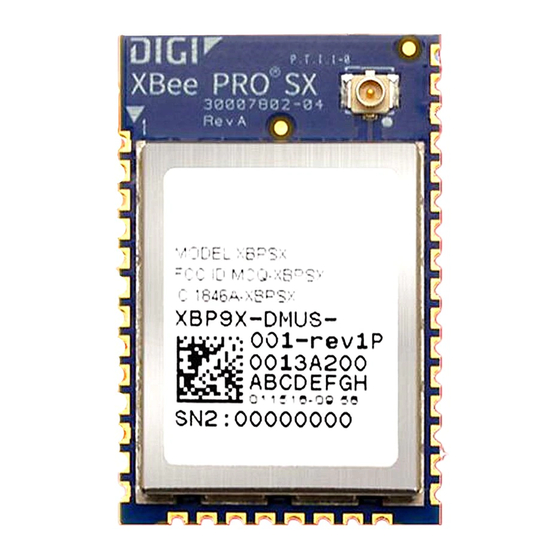
Related Manuals for Digi Digi XBee SX


Summary of Contents for Digi Digi XBee SX
- Page 1 XBee Radio Frequency (RF) Modems XBee-PRO SX RF Modem User Guide...
-
Page 2: Customer Support
Information in this document is subject to change without notice and does not represent a commitment on the part of Digi International. Digi provides this document “as is,” without warranty of any kind, expressed or implied, including, but not limited to, the implied warranties of fitness or merchantability for a particular purpose. -
Page 3: Table Of Contents
Contents XBee RF Modems User Guide Applicable firmware and hardware Regulatory approvals General XBee RF Modem specifications Power requirements Communication interface specifications Physical properties XBee-PRO SX RF Modem specifications Networking specifications Performance specifications Hardware Front view (RS-232/RS-485 variant) Power connector RS-232/RS-485 serial port RJ-45 pin signals Front view (Analog/Digital I/O variant) Analog and Digital I/O ports... - Page 4 Operation Commissioning Pushbutton behavior XBee-PRO SX RF Modem Interfacing protocols RS-232 operation RS-485 (2-wire) half-duplex operation RS-485 (4-wire) full-duplex operation RS-485 connection guidelines Analog input single-ended voltage operation Analog input current loop operation Analog input differential voltage operation Digital input operation Digital sinking driver output operation Configure analog and digital modes Analog and digital I/O sampling...
-
Page 5: Xbee Rf Modems User Guide
XBee RF Modems User Guide The XBee RF Modem is an enclosed, compact solution that includes an XBee RF Module and supports communication with systems using RS-232, RS-485, USB, analog input, and digital I/O interfaces. The modem's on-board XBee RF module transmits and receives data from other devices on the same wireless network, allowing you to easily make your existing wired systems wireless. -
Page 6: Communication Interface Specifications
XBee RF Modems User Guide General XBee RF Modem specifications Specification Condition Value Supply voltage range 7-30 VDC Typical supply voltage 12 V Receive current VCC = 12 V 20 mA Transmit current VCC = 12 V 300 mA Sleep current VCC = 12 V 5 mA Communication interface specifications... -
Page 7: Physical Properties
XBee RF Modems User Guide XBee-PRO SX RF Modem specifications Specification Condition Value Maximum: 31 V Absolute voltage rating (each pin) Minimum: -0.5 V Input impedance ~1 MΩ Digital outputs Output type Open collector sinking driver Maximum sink current 200 mA Maximum supply voltage for external pull-up resistor 31 V Resistor pull-ups (switch selectable) -
Page 8: Performance Specifications
XBee RF Modems User Guide XBee-PRO SX RF Modem specifications Specification Value Supported network Peer-to-peer (master/slave relationship not required), point-to-point/point- topologies (software to-multipoint, mesh selectable) Optional 256-bit Advanced Encryption Standard (AES) cipher block chaining Encryption (CBC) Encryption. Use the EE command to enable encryption. Use the KY command to set the encryption key. -
Page 9: Hardware
Hardware Front view (RS-232/RS-485 variant) Front view (Analog/Digital I/O variant) Back view (all variants) XBee RF Modems User Guide... -
Page 10: Front View (Rs-232/Rs-485 Variant)
Hardware Front view (RS-232/RS-485 variant) Front view (RS-232/RS-485 variant) Number Function RS-232/RS-485 serial port Power connector Power connector 7 - 30 VDC power connector RS-232/RS-485 serial port CAUTION! The RJ-45 port is only for RS-232/RS-485 connections. If you plug in any Power over Ethernet (PoE) connection, it will damage the port. -
Page 11: Rj-45 Pin Signals
RJ-45 pin signals The following table describes the pin signals of the RJ-45 connector. Low-asserted signals are distinguished with a horizontal line over the signal name. For more information on how to use the RS-232 and/or RS-485 functions on the modem, see Interfacing protocols. -
Page 12: Front View (Analog/Digital I/O Variant)
Hardware Front view (Analog/Digital I/O variant) Front view (Analog/Digital I/O variant) Number Function Analog and digital I/O ports Power connector Analog and Digital I/O ports Phoenix 10-pin connector. Power connector 7-30 VDC power connector. Phoenix 10-pin connector signals The following table describes the pin signals of the Phoenix 10-pin connector. For more information on how to use the Analog and/or Digital functions on the modem, see Interfacing protocols. -
Page 13: Back View (All Variants)
Hardware Back view (all variants) Name Function Single-ended voltage input Analog input 1 Current loop input Differential voltage pair 1 positive terminal Single-ended voltage input Analog input 2 Current loop input Differential voltage pair 1 negative terminal Single-ended voltage input Analog input 3 Current loop input Differential voltage pair 2 positive terminal... -
Page 14: Rssi Leds
Hardware Back view (all variants) RSSI LEDs RSSI LEDs indicate the amount of fade margin present in an active wireless link. Fade margin is the difference between the incoming signal strength and the modem's receiver sensitivity. 3 LEDs ON = Very Strong Signal (> 30 dB fade margin) 2 LEDs ON = Strong Signal (>... -
Page 15: Getting Started With The Xbee Rf Modem
Getting started with the XBee RF Modem Kit requirements Identify the kit contents Connect to the USB port Connect to the RS-232 port Configure the device using XCTU Configure a network XBee RF Modems User Guide... -
Page 16: Kit Requirements
Getting started with the XBee RF Modem Kit requirements Kit requirements System requirements The software mentioned in this guide is compatible with the following operating systems: Windows Vista or higher (32-bit or 64-bit versions) Mac OS X v10.6 and higher versions (64-bit version only) Linux with KDE or GNOME window managers (32-bit or 64-bit versions) Additional requirements This guide assumes the use of at least two XBee RF Modems. -
Page 17: Connect To The Rs-232 Port
Getting started with the XBee RF Modem Connect to the RS-232 port 1. Connect the antenna to the RPSMA connector on the XBee RF Modem. 2. Plug the 12 V power supply into the power jack. 3. Connect the mini USB cable from a PC to the USB port on the RF Modem. Connect to the RS-232 port In order to properly connect the modem for this guide: 1. -
Page 18: Configure The Device Using Xctu
XBee Configuration and Test Utility (XCTU) is a multi-platform program that enables users to interact with Digi radio frequency (RF) devices through a graphical interface. The application includes built-in tools that make it easy to set up, configure, and test Digi RF devices. - Page 19 Getting started with the XBee RF Modem Configure the device using XCTU 2. Select the serial ports you would like to scan for radio modules. Click Next. XBee RF Modems User Guide...
- Page 20 Getting started with the XBee RF Modem Configure the device using XCTU 3. Select any port parameters you would like to include in the search process. Note XCTU displays estimated discovery time in the Set port parameters dialog. Adding more port parameters to the search increases discovery time.
-
Page 21: Configure A Network
Getting started with the XBee RF Modem Configure a network 4. Click Finish to initiate the discovery scan. A new dialog opens, displaying devices found and estimated time remaining. You can click Stop to halt the discovery process at any time. For example, you can stop the process if the modules you were looking for are already found. - Page 22 Getting started with the XBee RF Modem Configure a network 5. Repeat the process for the other modem (Modem 2). 6. Select the DH (Destination Address High) of Modem 1 and type the SH of Modem 2. 7. Select the DL (Destination Address Low) of Modem 1 and type the SL of Modem 2. 8.
- Page 23 Operation WARNING! When operating at 1 W power output, observe a minimum separation distance of 6 ft (2 m) between devices. Transmitting in close proximity of other devices can damage the device's front end. Commissioning Pushbutton behavior Interfacing protocols XBee RF Modems User Guide...
-
Page 24: Operation
Operation Commissioning Pushbutton behavior Commissioning Pushbutton behavior The Commissioning Pushbutton performs multiple functions to identify and configure the XBee RF Modem in an XBee network. Button presses and actions for each XBee RF modem vary as shown in the following table. Consecutive button presses must occur within two seconds of each other to perform the desired action. -
Page 25: Rs-232 Operation
Operation Interfacing protocols Digital input Digital sinking driver output This section introduces XBee module concepts and commands. See the product manual for your XBee module for additional information. RS-232 operation The RS-232/RS-485 variant of the XBee RF Modem defaults to RS-232 mode. If the modem is not set to RS-232 mode, set the D2 command to 4. -
Page 26: Rs-485 (2-Wire) Half-Duplex Operation
Operation Interfacing protocols The following diagram shows a sample wireless connection: DTE <--> DCE DCE <--> DCE RS-485 (2-wire) half-duplex operation To set the RS-232/RS-485 variant of the XBee RF Modem to RS-485 (2-wire) half-duplex mode, set the D2 and D3 commands to 5 and the D7 command to 7. The USB port can be used to configure the RS- 485 (2-wire) mode, but while it is plugged in the RS-485 (2-wire) protocol will not function. -
Page 27: Rs-485 (4-Wire) Full-Duplex Operation
Operation Interfacing protocols RS-485 (2-wire) wiring diagram RS-485 (4-wire) full-duplex operation To set the RS-232/RS-485 variant of the XBee RF Modem to RS-485 (4-wire) full-duplex mode, set the D2 command to 5, the D3 command to 4, and the D7 command to 7. The USB port can be used to configure the RS-485 (4-wire) mode, but while it is plugged in the RS-485 (4-wire) protocol will not function. -
Page 28: Analog Input Single-Ended Voltage Operation
Operation Interfacing protocols 1. Use twisted pair cabling for positive and negative data lines (Ethernet cables are good for twisted pairs). 2. For the RS-485 (2-wire) variant, select wires so that Data+ and Data- are connected to a twisted pair. 3. -
Page 29: Digital Input Operation
Operation Interfacing protocols same number as Analog Input 2; Differential Voltage 2 is the same number as Analog Input 3; Differential Reference 2 is the same number as Analog Input 4. Read the appropriate hex values and use the following equation to convert the reading into the differential voltage: Analog and digital I/O sampling for information on how to properly read the IS command. - Page 30 Operation Interfacing protocols Command Command parameter Signal pin Pin # Function/mode parameter value Analog input 2 Single-ended voltage Current loop Differential voltage Analog input 3 Single-ended voltage Current loop Differential voltage Analog input 4 Single-ended voltage Current loop Differential voltage XBee RF Modems User Guide...
-
Page 31: Analog And Digital I/O Sampling
Operation Interfacing protocols Command Command parameter Signal pin Pin # Function/mode parameter value D4 * Digital I/O 1 Input Low sinking driver output Pull-up output enable D9 * Digital I/O 2 Input Low sinking driver output Pull-up output enable P1 * Digital I/O 3 Input Low sinking driver output... - Page 32 Operation Interfacing protocols Field Name Description Digital 16-bit Hexadecimal number that indicates which digital I/O lines has sampling channel enabled. Each bit corresponds to one digital I/O line on the device. Below is a list mask of the digital input bits that are needed in this modem. The rest of the bits are not important for this modem.
-
Page 33: Certifications
Certifications FCC (United States) Industry Canada (IC) ACMA (Australia) XBee RF Modems User Guide... -
Page 34: Fcc (United States)
(2) this device must accept any interference received, including interference that may cause undesired operation. Modifications (FCC 15.21) Changes or modifications to this equipment not expressly approved by Digi may void the user’s authority to operate this equipment. XBee RF Modems User Guide... -
Page 35: Xbee Rf Modem Approved Antennas (30 Dbm Maximum Rf Power)
Digi does not carry all of these antenna variants. Contact Digi Sales for available antennas. Dipole antennas All antenna part numbers followed by an asterisk (*) are not available from Digi. Consult with an antenna manufacturer for an equivalent option. Part Number... - Page 36 9.0 dB Fixed/Mobile A09-Y14TM* 14 element Yagi 14.0 dBi RPTNC 9.9 dB Fixed/Mobile Omni-directional base station antennas All antenna part numbers followed by an asterisk (*) are not available from Digi. Consult with an antenna manufacturer for an equivalent option.
- Page 37 Part Number Type Gain Connector Required Antenna Cable Loss Application A09-F0NF* Fiberglass Base Station 0 dBi Fixed A09-F1NF* Fiberglass Base Station 1.0 dBi Fixed A09-F2NF-M Fiberglass Base Station 2.1 dBi Fixed A09-F3NF* Fiberglass Base Station 3.1 dBi Fixed A09-F4NF* Fiberglass Base Station 4.1 dBi Fixed A09-F5NF-M...
- Page 38 7.1 dBi RPTNC 1.9 dB Fixed Dome antennas All antenna part numbers followed by an asterisk (*) are not available from Digi. Consult with an antenna manufacturer for an equivalent option. Part Number Type Gain Connector Required Antenna Cable Loss...
- Page 39 Part Number Type Gain Connector Required Antenna Cable Loss Application A09-QRAMM 3" Quarter wave wire 2.1 dBi MMCX Fixed/Mobile A09-QRSM-2.1* Quarter wave 2.1" right angle 3.3 dBi RPSMA 0.4 dB Fixed/Mobile A09-QW* Quarter wave wire 1.9 dBi Permanent - Fixed/Mobile A09-QSM-3* Quarter wave straight 1.9 dBi RPSMA...
-
Page 40: Industry Canada (Ic)
RCM mark on an end product, a company must comply with a or b below: a. have a company presence in Australia. b. have a company/distributor/agent in Australia that will sponsor the import of the end product. Contact Digi for questions related to locating a contact in Australia. XBee RF Modems User Guide... -
Page 41: Troubleshooting
Troubleshooting This section contains troubleshooting steps for the XBee RF Modem. Reset the XBee RF Modem XBee RF Modems User Guide... -
Page 42: Reset The Xbee Rf Modem
Troubleshooting Reset the XBee RF Modem Reset the XBee RF Modem If the XBee RF Modem loses its connection to the computer, you can attempt a reset. Condition The XBee RF Modem loses connection to the computer. Solution Each XBee RF Modem has a reset button. The following image shows the location of the reset button as 1, the top button.
Need help?
Do you have a question about the Digi XBee SX and is the answer not in the manual?
Questions and answers