Table of Contents
Advertisement
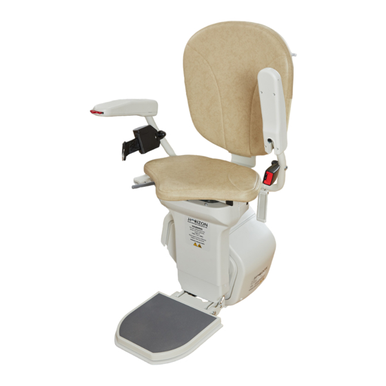
AmeriGlide
HORIZON PLUS
Installation Manual
WARNING: YOU MUST READ THIS
INSTALLATION MANUAL BEFORE
STARTING TO INSTALL THE STAIR LIFT.
ameriglide.com/horizon-plus-install-video
Please download the most current Installation Manual at
ameriglide.com/horizon-plus-install
Please have manual at hand if you call Technical Support.
Technical Support
1 (800) 791-6419
8AM-5PM EST / Monday-Friday
VER052119
Accessibility
Solutions
HORIZON PLUS
INSTALLATION VIDEO
Advertisement
Table of Contents

Related Manuals for AmeriGlide HORIZON PLUS


Summary of Contents for AmeriGlide HORIZON PLUS
- Page 1 AmeriGlide Accessibility Solutions HORIZON PLUS Installation Manual WARNING: YOU MUST READ THIS INSTALLATION MANUAL BEFORE STARTING TO INSTALL THE STAIR LIFT. HORIZON PLUS INSTALLATION VIDEO ameriglide.com/horizon-plus-install-video Please download the most current Installation Manual at ameriglide.com/horizon-plus-install Please have manual at hand if you call Technical Support.
- Page 2 ABOUT THE STAIRLIFT Meaning Meaning Arm Rests On/Off Switch (folds up and down) Directional Control Seat Swivel Levers Key Switch Lap Belt Rail Status Display Footrest Lever Mains Power Connection (Plus model only) Footrest Charging Point (folds up and down) Safety Edges Remote Control Hand Wind Point...
- Page 3 CONTROLS Mains Power Connection (13) The stairlift should be plugged in at the nearest socket. This could be at the top or bottom of the stairs. The lift needs to be plugged in and switched on at all times. When the power is on, a green indicator light will be shown on the power supply, mounted nearby.
- Page 4 SWIVEL SEAT Swivel Seat For safety, the seat is locked into one of two positions. In the normal travel position, the seat will be locked into position with your back parallel to the rail. This is so you do not catch your feet on the steps during travel. The lift will not travel unless the seat is locked into this position.
- Page 5 CHARGE POINTS & REMOTES Charging Points These (14) are located at the top and bottom of the track. The lift MUST be parked on a charging point when not in use. The stairlift will sound an audible beep if it is not parked on a charging point.
- Page 6 TYPICAL PACKAGE LIST A typical installation will use the following supplied parts: TOP JOINTING PLATE BOTTOM JOINTING PLATE RAIL LEGS END PLATE END CAPS MANUAL WINDING TOOL CHARGING SPLITTER REMOTE CONTROLS CHARGING POINT & BATTERIES END PLATE SCREWS GEAR LUBRICANT GEAR RACK LEG SCREWS BOLTS (EXTRA)
- Page 7 • 5 x Rail clamps • 4 x M4 x 10 Countersunk Hex screws • 5 x Legs • 2 x Remote controls & batteries • 5 x Leg mounts • 1 x Mains – 27v Transformer & bracket • 10 x M10 x 16 hex bolts •...
- Page 8 INSTALLATION EQUIPMENT To perform a typical installation you will need to use the following types of equipment: • Safety Goggles and Rigger Gloves • Spirit level, tape measure • Drill bits: - 8mm masonary drill bits (for drilling into brick, stone, concrete, etc) - No 3 Screwdriver bit and extension bar for drill to use on footplate screws •...
- Page 9 HEALTH & SAFETY GUIDANCE Electrical Safety Installation of the stairlift is mainly a manual process. Although you do need to plug the stairlift into a mains power supply socket, this socket MUST already have been installed by a qualified electrician. Safe Working Practices When installing the stairlift, follow safe working practices in these areas: •...
- Page 10 INSTALLING THE STAIRLIFT doors from opening and closing. Laying Out The Components Each stairlift consists of 3 boxes, the Drive Unit, the Chair and the Chassis Leg. The Chassis leg box also contains the parts kit. RAIL PARTS TOP RAIL SECTION BOTTOM RAIL SECTION GEAR RACK TOP JOINTING PLATE...
- Page 11 ASSEMBLED LEGS An Assembled and how it fits into the rail is shown below. These will be used in the next step. Make sure the legs are straight and then tighten, using two 13mm wrenches. This ensures that they do not move during installa- tion process.
- Page 12 FIT LEGS TO TOP RAIL SECTION Place assembled Legs onto the To p R ail S ec tio n. The Legs will rotate into place fully assembled. The lower end should be located so that it sits on the step above where the two rails will join.
- Page 13 SETTING CLEARANCE DISTANCES Ensure that each leg sits level on the correct step. Adjust until the rail is a minimum distance of 3 1/4” from the nose of the step when measured diagnonally. We recommend the rail should be mounted 4” from the wall, however 2.5”...
- Page 14 DRIVE UNIT UNPACK DRIVE UNIT Unpack Drive Unit and inspect the bottom of the Drive Unit to be sure limit switch buttons and springs are in place. DRIVE UNIT LIMIT SWITCH BUTTONS & SPRINGS LOAD DRIVE UNIT Load the Drive Unit at the top of the track carefully.
- Page 15 CONNECT BATTERY Remove Drive Unit covers by inserting an allen wrench into the holes and loosening the screws as shown to the right. Make the following connections: 1. Orange fuse link between black and red battery terminals 2. Red to +24v on PCB (Printed Circuit Board) INSERT ALLEN WRENCH TO LOOSEN DRIVE UNIT SIDE COVERS BATTERIES ROTATED TO MAKE CONNECTIONS...
- Page 16 UNPACK CHASSIS LEG Before mounting Chassis Leg, turn the two 4mm allen screws flush with the Remove Chassis Leg from packaging and remove plastic covers. inside of Chassis Leg frame. CHASSIS LEG ASSEMBLY Remove washers and nuts from Drive Unit bolts and Fit washers and nuts back onto the attach...
- Page 17 CHASSIS LEG WIRING If you ordered a powered swivel seat, please refer to next section, Electrical Connections - (Powered Option Units), for additional wiring. Match male 4 pin plug with Feed cables through Chassis Using supplied tie-wrap, secure corresponding female end and top hole.
- Page 18 ELECTRICAL CONNECTIONS - NON POWERED UNITS Pictured below are connections found beneath the seat on Non-Powered Units. Seat’s safety sensor connections. Arm’s Digital Display connections. ELECTRICAL CONNECTIONS - (POWERED OPTION UNITS) If the stairlift has a powered swivel, connect the swivel motor loom (Red & Black). Black - Black, Red - Red for a Right Hand Lift Black - Red, Red - Black for a Left Hand Lift.
- Page 19 ATTACH SEAT 1. Remove seat from packing and place on drive unit. Run cables through the hole in the seat. Line up screw holes between seat and leg chassis. 2. Fit Seat using 4 x 8mm hex bolts and tighten. 3.
- Page 20 SETTING SOFTWARE OPTIONS IMPORTANT - If your stair lift is not properly programmed in this step, the remotes will not function correctly. NOTE: If your lift is on the right side of the stair case... The cover with the on/off switch can only be removed if the unit is at the top of the rail. is attached to the arm with a tie wrap.
- Page 21 Attach bottom cover of drive Power ON unit. Insert and turn. train. Using the switch, move Power OFF unit. the unit down the rail approximately 1 foot. GEAR RACK NOTE: Before installing the gear racking, the chair needs to be completely assembled and powered on and moved down the rail a short distance.
- Page 22 INSTALL THE CHARGER NOTE: Before installing charger, lift must be parked midway on the stair case until charger installation is complete and tested. Run a measuring tape inside the rail from the top to the bottom. You will be attaching the charging cable to the end and pulling it back up using the measuring tape.
- Page 23 CHA RG E R P O S I T IV E C H A R G E R & C H A R G IN G ( fe m a le co n n ec to r ) W I R E G R O U N DS ( r i n g co n n e c tor ) C H AR G IN G W I R E P O S IT I V E...
- Page 24 CONNECTING CHARGE CIRCUIT (CONT.) Neatly stow wires inside of rail once connected. Attach ground wire of charging strip Insert charging strip and tighten down. Once again, it can on the other end of rail. not be closer than 2 ¾” from the end of the rail. See next page for clearance guidelines.
- Page 25 Charging Point Location Clearance Check that the upper surface of the footrest is less than 6 1/2” above the bottom and top landings. Charging Point deter- mines the height of the LESS stairlift finishing postion at the THAN bottom & top of the stairs. 6 1/2”...
- Page 26 Plug the charging strip wire into charging cable and tuck wires neatly into rail. Add end caps. Plug in and power on unit. Move lift down to charging strip. Once the chassis leg covers are back on, move the lift to the top of stairs and enusre that the seat swivels correctly.
- Page 27 2” from wall, bannister, or hand rail. Install batteries into the remotes and test. Enjoy using your Horizon Plus stair lift! TROUBLESHOOTING If after completion there is 27v on both charge points and the lift reads “off charge”, check the 7.5 amp fuse...
- Page 28 POWERED HINGE Use supplied wiring looms Cable 1 and connect as shown in the diagram below. Place Hinge PCB box into top of rail extrusion before fitting plastic end cover. Cable 2 Cable 3...
- Page 29 HINGE WIRING DIAGRAM Do not make any power hinge electrical connections with the lift parked on a charge point and the wall charger plugged in. Disconnect ALL power supplies.
- Page 30 OFFSET FOOTREST The footrest can be offset if necessary. Unhook lever linked footrest spring, remove screws holding footrest lever link bracket, disconnect footrest loom. Remove plastic footrest cover, remove footrest limit loom, slacken off grub screw. Tap mounting bar through bracket and remove footrest assembly, pull loom out of footrest, one connector at a time, remove 3 bolts and reposition bracket.
- Page 31 CHAIR ALTERATION Chair Ergonomic Alteration The chair can be individually tailored to better fit the customer or installation area. The arm rests can be widened or made shorter, and the seat pad can be moved forward. The arm rests can be made shorter and/or further apart by removing the 4 x allen bolts, repositioning the arms and replacing the bolts.
- Page 32 Chair Ergonomic Alteration (cont.) When using Positions 2, 4 & 6, the arm rest angle will need altering. Remove 4 x pozi screws in bottom of armrest cover. Remove armrest top. Remove bolt ...and replace here The Seat pad can be moved forwards. Undo the zips on the seat pad.
- Page 33 STAIRLIFT TEST RUN PT. 1 TEST RUNNING STAIRLIFT - EMPTY Press manual swivel levers and turn chair, make sure it locks securely at either end of travel and that the swivel interlock switch operates correctly. Key is attached to the arm with a tie wrap, detach and insert into keyswitch under armrest.
- Page 34 REMOTE CONTROLS Installing the Remote Controls There are 2 types of remote control, Infra-Red (IR) & Radio Frequency (RF). Each system comes with 2 remote controls as standard. More can be added if required. IR control is supplied as standard, RF control is an available option if local IR interference is causing an issue.
- Page 35 STAIRLIFT TEST RUN PT. 2 TEST RUNNING STAIRLIFT - FULLY LADEN Test running the stairlift fully laden (with someone in it) ensures the lift is working correctly, and that it clears any obstacles. It also begins the bedding in process. Please ensure that the rack is lubricated with the supplied silicone or synthetic PTFE based grease at this point.
- Page 36 WIRING DIAGRAM...
- Page 37 CONNECTION DIAGRAM On/Off Switch GROUND Black Black MOTOR B MOTOR A Black Carriage Motor & Brake Black Black Charge Pick-up White Right Hand Lift Red, Left Hand Lift Black Powered Swivel Motor Right Hand Lift Black, Black Left Hand Lift Red SEAT B SEAT A Right Hand Lift...
- Page 38 TECHNICAL INFORMATION Weight Limits The stairlift has been designed to carry one person only, in a seated position. The stairlift has a maximum weight limit of 300 lbs. Operating Periods/Excessive Use The stairlift has been designed to run for four minutes with a break of at least six minutes afterwards. If you use the stairlift too often without taking a break, the motor will not cool down between journeys and may become damaged.
- Page 39 TECHNICAL INFORMATION Outdoor Lifts The supplied cover must be used when the stairlift is not in use. Releasing a Trapped User If a user becomes trapped on the stairlift due to a fault, they should be assisted from the chair in the following way: •Lift one of the manual swivel levers and rotate the carriage towards the staircase until seat locks into swivelled position.
- Page 40 DIAGNOSTIC CODES Diagnostic Display These codes are displayed on the Diagnostics Display panel. Code Meaning No Display No power 1. Check the battery isolator switch is in the ‘I’ position. 2. Check batteries are correctly connected and in good order. 3.
- Page 41 Further diagnostics and settings are available by cycling through the menu system. Code Meaning Position 12345 Lifts current position on rail. Bottom end stop is 00000. Press and hold menu button to re-program. Remote 1/2/3/4 Shows current Remote channel selection. Press adjust button to change. Right / Left Hand Shows current installation hand selected.
- Page 42 SERVICING Servicing The Standard Horizon stairlift requires a service every months. If working on the drive unit while still mounted on the rail extrusion, it is advisable to move current HSE manual handling guidelines. Service Carriage • Remove carriage from rail. Turn off. Remove plastic side covers. •...
- Page 43 PURCHASER INFORMATION PRODUCT INFORMATION Name: ___________________________________________________ Model: ________________________________________________ Address: _________________________________________________ Serial Number: ________________________________________ __________________________________________________________ Purchase Date: ________________________________________ __________________________________________________________ Phone: __________________________________________________ INSTALLER INFORMATION Email: ___________________________________________________ Company Name: ______________________________________ Contact Name: ________________________________________ Phone: ________________________________________________ Email: _________________________________________________...
- Page 44 HORIZON PLUS INSTALLATION VIDEO ameriglide.com/horizon-plus-install-video Please download the most current Installation Manual at ameriglide.com/horizon-plus-install Please have manual at hand if you call Technical Support. Technical Support 1 (800) 791-6419 8AM-5PM EST AmeriGlide Accessibility Solutions 5110 Atlantic Avenue • Raleigh, NC 27616...
Need help?
Do you have a question about the HORIZON PLUS and is the answer not in the manual?
Questions and answers
need wiring diagram for battery hookup
The battery hookup for the AmeriGlide Horizon Plus involves the following connections:
1. Connect the orange fuse link between the black and red battery terminals.
2. Connect the red wire to +24V on the Printed Circuit Board (PCB).
3. Ensure the batteries are properly rotated and seated into the battery tray before replacing the top cover.
No additional wiring diagram details are provided in the context.
This answer is automatically generated
Installationanweisung in Deutsch