Table of Contents
Advertisement
Quick Links
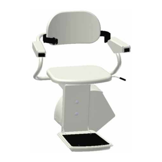
Escort Stair Lift
Installation Manual
Read and understand this manual thoroughly before attempting to install or operate the lift. If you have any questions,
please contact your Authorized AmeriGlide Dealer or AmeriGlide's Technical Service Department at 866-294-4460.
P 866-294-4460 | www.ameriglide.com
Advertisement
Table of Contents

Subscribe to Our Youtube Channel
Related Manuals for AmeriGlide Escort


Summary of Contents for AmeriGlide Escort
- Page 1 Escort Stair Lift Installation Manual Read and understand this manual thoroughly before attempting to install or operate the lift. If you have any questions, please contact your Authorized AmeriGlide Dealer or AmeriGlide's Technical Service Department at 866-294-4460. P 866-294-4460 | www.ameriglide.com...
-
Page 2: Table Of Contents
INDICATIONS OF USE STATEMENT Adjusting the Gear Rack ....37-38 The Escort Stair Lift assists with the transfer of patients or mobility impaired persons, up and down SERVICE NOTES between levels of a residential or private facility. -
Page 3: Installation & Application Notes
Electrical equipment shall be certifi ed to the requirements of CAN/CSA B44.1/ASME A17.5. ASME 18.1 REQUIREMENTS INSTALLATION REGULATIONS The Escort lift is an incline stairway chair lift for private residence use only. Installation of this lift must comply to the following American Society of Mechanical Engineers ASME 18.1 – 2011 "safety standard for platform lifts and stairway chair lifts". -
Page 4: Preparation
Slotted Screwdriver - #1 or 2 size Set of Hex Wrenches Measuring tape or ruler Level 3/8” power drill Metal cutting saw (hacksaw) Square Safety Glasses Volt meter Hammer Utility knife Escort Stair Lift Installation Manual AmeriGlide | www.ameriglide.com | 866-294-4460... -
Page 5: What's In The Box
18. Flat Washers (2) 19. Thrust Roller Bearing (1) 20. Copper Based Antisieze Lubricant (1) Box 2 21. Seat Assembly (1) (Escort shown) Box 3 (not shown) 22. 2 Aluminum Rails - Installations over 16 feet will be shipped with 3 or 4 rails, depending on installation requirements 23. -
Page 6: Getting To Know The Rail
Use these to fasten the end caps using these channels. Positive charging strip will rest onto the rail. inside these channels. 9. Main Interior Wire Channel Used for running wiring up and down the rail. Escort Stair Lift Installation Manual AmeriGlide | www.ameriglide.com | 866-294-4460... -
Page 7: Preparing The Rail
This rail can be removed and discarded. It is easiest to prepare the rail in an open environment such as a room or outdoors unless maneuverability of the full rail will be cumbersome. TEC0016 20160714 P/N: 630-00039 Rev C Escort Stair Lift Installation Manual... - Page 8 [Figure 8-3]. Secure the limit cams with Figure 8-2 (2) 10-24 screws and square nuts (provided). The position of the limit cam can be adjusted later if needed. Figure 8-3 LIMIT CAM CHANNEL Escort Stair Lift Installation Manual AmeriGlide | www.ameriglide.com | 866-294-4460...
- Page 9 Otherwise, excess wire can be tucked into the inside of the rail. [Figure 9-1] Figure 9-1 Align end cap screw holes precisely. Do not overtighten. CAUTION END CAP SCREW CHANNELS TEC0016 20160714 P/N: 630-00039 Rev C Escort Stair Lift Installation Manual...
- Page 10 6. Tighten the one loose gear rack screw with the provided 9/64" hex wrench. Figure 10-3 Be careful not to pinch wires when sliding rails together. CAUTION MAIN INTERIOR WIRE CHANNEL SPLICE BAR CHANNELS Figure 10-4 Escort Stair Lift Installation Manual AmeriGlide | www.ameriglide.com | 866-294-4460...
- Page 11 Loosening the bracket bolts will help them slide easier. A short piece of 2 x 4 may also be used to gently tap the brackets into place. RAIL BRACKET CHANNELS TEC0016 20160714 P/N: 630-00039 Rev C Escort Stair Lift Installation Manual...
-
Page 12: Installation
(three (3) per bracket). bolts (three (3) per bracket). Escort Stair Lift Installation Manual AmeriGlide | www.ameriglide.com | 866-294-4460... -
Page 13: Installing The Chassis
2. Using the provided tool or a 7mm socket attached to your drill and extension, turn the end of the motor shaft until the wheels are within the rail. Figure 13-3 TEC0016 20160714 P/N: 630-00039 Rev C Escort Stair Lift Installation Manual... - Page 14 [Figure 14-2] 4. With a torque wrench and 9/16" socket tighten each bolt to between 35 and 50 ft-lb of torque. q SUPPORT MOUNTING SCREWS ARE SECURE Escort Stair Lift Installation Manual AmeriGlide | www.ameriglide.com | 866-294-4460...
- Page 15 Three star washers must be located between chassis and seat support and bolts must be torqued as specifi ed to prevent serious bodily WARNING injury. [Figure 15-1] Star Washers s [Figure 15-1] TEC0016 20160714 P/N: 630-00039 Rev C Escort Stair Lift Installation Manual...
-
Page 16: Installing The Chair
Installation INSTALLING THE CHAIR INSTALLING THE CHAIR LATCH SCREW LATCH SPRING LOOP Escort stair lifts are confi gured as a left or right handed unit and cannot be changed. Contact Ameriglide's technical service WARNING department at 866-294-4460 to change confi guration 1. - Page 17 NOTE: Refer to page 26 if the unit does not beep. Figure 17-5 LATCH SCREW ENGAGES LATCH SLOTS WHEN SEAT IS ROTATED UNIT DOES NOT OPERATE WHEN SEAT IS ROTATED LATCH SPRING APPLYS PRESSURE TO LATCH SCREW TEC0016 20160714 P/N: 630-00039 Rev C Escort Stair Lift Installation Manual...
-
Page 18: Re-Installing The Charging Strips
Wire Channel as you go. Be sure the wire is all the way in leaving only the end piece with the 2-pin connector outside the rail. [Figure 18-2] Figure 18-1 Figure 18-2 CHARGING STRIP CHANNELS Escort Stair Lift Installation Manual AmeriGlide | www.ameriglide.com | 866-294-4460... -
Page 19: Installing The Upper Limit Cam
A tube of lubricant is provided in the chassis box. Lightly lubricate the entire gear rack by squeezing the tube onto the gear rack. Figure 19-2 LIMIT CAM CHANNEL Figure 19-3 TEC0016 20160714 P/N: 630-00039 Rev C Escort Stair Lift Installation Manual... -
Page 20: Installing The End Cap/Bracket Cap Option
2. Place the bracket cover over the outside of the bottom piece of the bracket and slide it down until it snaps into place. 3. Repeat on all brackets. Escort Stair Lift Installation Manual AmeriGlide | www.ameriglide.com | 866-294-4460... -
Page 21: Charging System
NOTE: The power supply should be connected to an outlet at all times and the switch on the back of the Figure 20-1 chassis must remain on for the batteries to charge. TEC0016 20160714 P/N: 630-00039 Rev C Escort Stair Lift Installation Manual... -
Page 22: Completion Checklist
The footrest safety pan stops lift when obstructed in each direction. The lift stops when it comes in contact with the limit cams. All electrical wires are clear of moving parts. Escort Stair Lift Installation Manual AmeriGlide | www.ameriglide.com | 866-294-4460... -
Page 23: Verifying Operation
Always use the seat belt and remain seated in the center of the seat. DIRECTION CONTROLS The Escort Stair Lift is equipped with an armrest mounted control and two wireless remote controls. All controls are constant pressure. To prevent accidental movement, the lift has a programmed delay before moving. -
Page 24: Required Maintenance
To prevent electrical shock or damage to the lift, disconnect the 120 VAC power when cleaning the lift. Never apply cleaning liquids directly on the rail mounted charging stations SHOCK or electrical safety switches. HAZARD Escort Stair Lift Installation Manual AmeriGlide | www.ameriglide.com | 866-294-4460... - Page 25 [Figure 25-3] 4. Refer back to the INSTALLING THE CHAIR section (page 16) for applying the lubrication and reinstalling the seat. [Figure 25-3] TEC0016 20160714 P/N: 630-00039 Rev C Escort Stair Lift Installation Manual...
-
Page 26: Audio Alert
If your lift fails to reset, contact your dealer for service. NOTE: A fault is defi ned as major any time it requires the unit to be turned off and back on to reset. Escort Stair Lift Installation Manual AmeriGlide | www.ameriglide.com | 866-294-4460... -
Page 27: Remote Control Programming
11. Aim the second IR remote at the chassis, press and release the UP or Down button. Two beeps should sound indicating the second remote is programmed. TEC0016 20160714 P/N: 630-00039 Rev C Escort Stair Lift Installation Manual... -
Page 28: Manual Lowering Tool
3. Place the manual lowering tool onto the end of the motor shaft and rotate until the fi nal limit switch becomes disengaged. Figure 28-1 4. Re-install the plastic plug and turn the lift "ON". Escort Stair Lift Installation Manual AmeriGlide | www.ameriglide.com | 866-294-4460... -
Page 29: Cutting The Rail
Appendix I CUTTING THE RAIL APPENDIX I Measuring Cutting the Rail The following section is for installations where the rail has not been ordered pre-cut. TEC0016 20160714 P/N: 630-00039 Rev C Escort Stair Lift Installation Manual... -
Page 30: Measuring The Rail
Seat column of the Rise and Run Chart Key is BOX 3 the length of rail that must be added for each additional inch of seat height. The maximum allowable overrun is 12 inches. • Escort Stair Lift Installation Manual AmeriGlide | www.ameriglide.com | 866-294-4460... -
Page 31: Flight Angle Charts
30<36° where splice joints are located, to ensure a smooth transition between rails. Rail length cannot be cut 4 inches 2 1/4 inches 25<30° to less than 36 inches. TEC0016 20160714 P/N: 630-00039 Rev C Escort Stair Lift Installation Manual... - Page 32 When removing the gear rack DO NOT remove the screws from the gear rack. If you do, the fastening plate will become lost within the channel and the gear rack will need to be removed. Escort Stair Lift Installation Manual AmeriGlide | www.ameriglide.com | 866-294-4460...
- Page 33 LICE J TOP SECTION P SECT 96" STANDARD LENGTH 36" MINIMUM CUT LENGTH Remember to keep the factory cuts together at the splice joint to assure the smoothest transition. TEC0016 20160714 P/N: 630-00039 Rev C Escort Stair Lift Installation Manual...
- Page 34 TOP SECTION P SECT 96" STANDARD LENGTH 36" MINIMUM CUT LENGTH 60.25" MINIMUM CUT LENGTH Remember to keep the factory cuts together at the splice joints to assure the smoothest transition. Escort Stair Lift Installation Manual AmeriGlide | www.ameriglide.com | 866-294-4460...
-
Page 35: Appendix Ii
Appendix II CUTTING THE GEAR RACK APPENDIX II Cutting and Adjusting the Gear Rack The following section is for installations where the rail has not been ordered pre-cut. TEC0016 20160714 P/N: 630-00039 Rev C Escort Stair Lift Installation Manual... -
Page 36: Cutting The Gear Rack
2. Cut either one or two pieces of gear rack depending on your confi guration. 3. Insert the gear rack pieces into the top of the rail. 4. Lightly tighten the rack with the hex screws. Escort Stair Lift Installation Manual AmeriGlide | www.ameriglide.com | 866-294-4460... -
Page 37: Adjusting The Gear Rack
Left hand installation = 1-1/2 in. Maximum Right hand installation = 1-1/2 in. Maximum Right hand installation = 9 in. Maximum Figure 37-2 Figure 37-3 Left Hand Install Shown Left Hand Install Shown TEC0016 20160714 P/N: 630-00039 Rev C Escort Stair Lift Installation Manual... - Page 38 9. Move the end stop to the end of the gear rack and tighten in place with a 9/64" hex wrench. [Figure 38-3] Figure 38-2 Figure 38-3 ALL GEAR RACK MOUNTING SCREWS ARE SECURE TOP AND BOTTOM GEAR RACK SPACING IS CORRECT Escort Stair Lift Installation Manual AmeriGlide | www.ameriglide.com | 866-294-4460...
-
Page 39: Service Notes
Service Notes Service Description: Service Date: Performed By: Service Description: Service Date: Performed By: Service Description: Service Date: Performed By: TEC0016 20160714 P/N: 630-00039 Rev C Escort Stair Lift Installation Manual... - Page 40 Escort Stair Lift Installation Manual TEC0016 20160714 P/N: 630-00039 REV C...
Need help?
Do you have a question about the Escort and is the answer not in the manual?
Questions and answers