Table of Contents
Advertisement
Quick Links
400 SERIES
CLAMP METER
41911
IMPORTANT: Please read these instructions carefully to ensure the safe and effective use of this product and save
these instructions for future reference. This manual has been compiled by Draper Tools and is an integrated part of the
product with which it is enclosed and should be kept with it for future references.
This manual describes the purpose for which the product has been designed and contains all the necessary information
to ensure its correct and safe use. We recommend that this manual is read before any operation or, before performing
any kind of adjustment to the product and prior to any maintenance tasks. By following all the general safety
instructions contained in this manual, it will ensure both product and operator safety, together with longer life of the
product itself.
AlI photographs and drawings in this manual are supplied by Draper Tools to help illustrate the operation of the product.
Whilst every effort has been made to ensure accuracy of information contained in this manual, the Draper Tools policy
of continuous improvement determines the right to make modifications without prior warning.
Advertisement
Table of Contents

Related Manuals for Draper 41911


Summary of Contents for Draper 41911
- Page 1 IMPORTANT: Please read these instructions carefully to ensure the safe and effective use of this product and save these instructions for future reference. This manual has been compiled by Draper Tools and is an integrated part of the product with which it is enclosed and should be kept with it for future references.
-
Page 2: Title Page
Commercial copying, redistribution, hiring or lending is prohibited. No part of this publication may be stored in a retrieval system or transmitted in any other form or means without written permission from Draper Tools Limited. In all cases this copyright notice must remain intact. -
Page 3: Table Of Contents
2. CONTENTS 2.1 CONTENTS ................Page content Page TITLE PAGE INTRODUCTION ....................2 REVISION HISTORY ..................2 UNDERSTANDING THIS MANUAL ..............2 COPYRIGHT NOTICE ..................2 CONTENTS CONTENTS ......................3 GUARANTEE GUARANTEE...................... 4 INTRODUCTION GENERAL SPECIFICATIONS .................5-7 HEALTH & SAFETY INFORMATION SAFETY PRECAUTIONS ................... -
Page 4: Guarantee
3. GUARANTEE 3.1 GUARANTEE Draper tools have been carefully tested and inspected before shipment and are guaranteed to be free from defective materials and workmanship. Should the tool develop a fault, please return the complete tool to your nearest distributor or contact Draper Tools Limited, Chandler's Ford, Eastleigh, Hampshire, SO53 1YF. -
Page 5: Introduction
4. INTRODUCTION 4.1 GENERAL SPECIFICATIONS Use of environmental conditions: 600V CAT.III Pollution Degree: II. Altitude <2000m. Working temperature and humidity: 0 ~ 40℃. (<80% RH, <10 ℃ is not considered). Storage temperature and humidity: -10 ~ 60℃. (<70% RH, removing the battery). Temperature coefficient: 0.1 Accuracy / ℃. - Page 6 4. INTRODUCTION AC Voltage Range Accuracy Resolution 400mV ±(1.5% rdg + 10 digit) 0.1m 0.001V ±(1.5% rdg + 5 digit) 0.01V 400V 0.1V 600V Input Impedance : 10MΩ Maximum Input Voltage : 600V DC or AC RMS Frequency Response : 40Hz~400Hz, Sinusoidal RMS (Average Responding) Notice :...
- Page 7 4. INTRODUCTION Diode and Continuity Test Function Range Resolution Accuracy Diode 0.001V Shows the approximate forward voltage drop of the diode. When the built-in buzzer sounds, Open circuit voltage: about 0.5V the measured resistance is less than 50Ω. Overload protection: 600V AC or DC RMS. Frequency/Duty Range Accuracy...
-
Page 8: Health & Safety Information
5. HEALTH & SAFETY INFORMATION Warning To avoid electrical shock or personal injury. Please read the safety information and “warnings and precautions” before use. This is an AC-DC current digital clamp meter (hereinafter referred to as the clamp meter). The whole circuit design is based on LSI A / D converter with full-scale overload protection circuit and frequency measurement function. -
Page 9: Identification
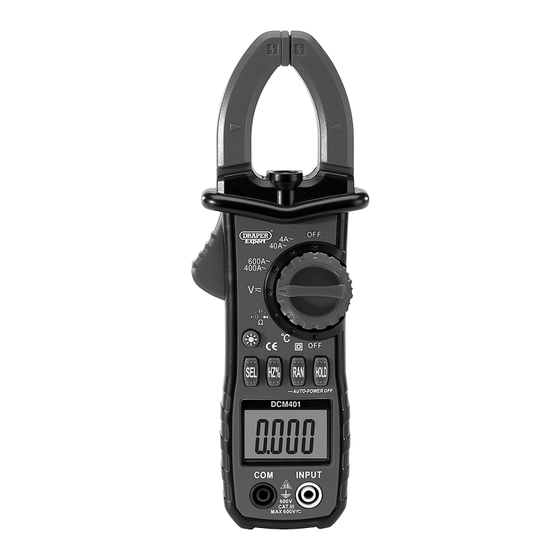
6. IDENTIFICATION Measurement clamp head. Measuring function selection dial. Inspection light. Back light & work light. Protection Guard: Protects the user's Function buttons. hand from touching the danger zone. Display. Clamp trigger. Probe sockets. -
Page 10: Lcd
6. IDENTIFICATION 6.1 LCD (Liquid-crystal display) - FIG. 1 FIG.1 Battery low indicator. Units of measurement indicator. Automatic range indicator. DC signal measurement indicator. LED indicator. Negative indicator. Continuity checking indicator. AC signal indicator. Data hold indicator. Numerical display. -
Page 11: Unpacking & Checking
Carefully remove the product from the packaging and examine it for any sign of damage caused during shipping. Lay the contents out and check them. If any part is damaged or missing, do not attempt to use the tool and contact the Draper Helpline immediately (see back page for details). -
Page 12: Operation Instructions
8. OPERATING INSTRUCTIONS 8.1 BACK LIGHT AND INSPECTION LIGHT. Press and hold the button to switch on and off the back light/inspection light. Note: The inspection light will only come on while in AC current function. 8.2 AUTOMATIC SHUTDOWN. If the meter is not used for approx. 30 minutes the meter will automatically shut down. The meter will give a warning buzz approx. -
Page 13: Resistance Measurement
8. OPERATING INSTRUCTIONS 8.6 RESISTANCE MEASUREMENT: Warning Risk of electric shock. When measuring the impedance on the line, make sure that the circuit power is off and the capacitors on the circuit are fully discharged. 1. Rotate the measurement function selection dial to the resistance (Ω) position and ensure that the power to the circuit under test is off. -
Page 14: Diode Test
8. OPERATING INSTRUCTIONS 8.9 DIODE TEST: Warning Risk of electric shock. When measuring diodes in line, make sure that the circuit power is off and the capacitors on the circuit are fully discharged. 1. Rotate the measurement function selection dial to the diode, ( ) position, press the "SEL"... -
Page 15: Maintenance
9. MAINTENANCE 9.1 REPLACEMENT BATTERY Warning To avoid false readings that may result in electric shock or personal injury, replace the battery as soon as the“ ” symbol appears on the meter display. Follow these steps to replace the battery: 1. -
Page 16: Explanation Of Symbols
10. EXPLANATION OF SYMBOLS 10.1 KEY EXPLANATIONS Button Operation "SEL" button: Function selection key, press "SEL" button, with the rotary switch measurement function to work in a trigger way. "Hz /%" button: Frequency / duty cycle selection key, in voltage or current range, press this key can make the selection on voltage / frequency / duty cycle or current / frequency / duty cycle measurement mode to work in a trigger way. -
Page 17: Explanation Of Symbols
10. EXPLANATION OF SYMBOLS 10.2 EXPLANATION OF SYMBOLS WEEE Voltage AC. Do not dispose of Waste Electrical & Electronic Equipment in with domestic rubbish. Voltage DC. For indoor use. Do not expose to rain. Current AC. Class II construction (Double insulated). Conforms to all relevant Current DC. -
Page 18: Disposal
11. DISPOSAL 11.1 DISPOSAL - At the end of the machine’s working life, or when it can no longer be repaired, ensure that it is disposed of according to national regulations. - Contact your local authority for details of collection schemes in your area. In all circumstances: •... - Page 19 NOTES...
- Page 20 ©Published by Draper Tools Limited. No part of this publication may be reproduced, stored in a retrieval system or transmitted in any form or by any means, electronic, mechanical photocopying, recording or otherwise without prior permission in writing from Draper Tools Ltd.
Need help?
Do you have a question about the 41911 and is the answer not in the manual?
Questions and answers