Advertisement
INSTRUCTIONS FOR
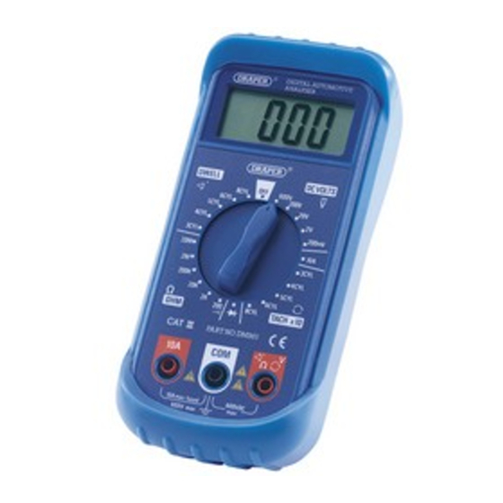
Digital Automotive
Analyser
Stock No.50024 Part No.DMM5
IMPORTANT: PLEASE READ THESE INSTRUCTIONS CAREFULLY TO ENSURE THE SAFE AND
EFFECTIVE USE OF THIS PRODUCT.
09/2004
GENERAL INFORMATION
This manual has been compiled by Draper Tools and is an integrated part of the product with which it is enclosed and
should be kept with it for future references.
This manual describes the purpose for which the product has been designed and contains all the necessary information
to ensure its correct and safe use. We recommend that this manual is read before any operation or, before performing
any kind of adjustment to the product and prior to any maintenance tasks. By following all the general safety instructions
contained in this manual, it will ensure both product and operator safety, together with longer life of the product itself.
All photographs and drawings in this manual are supplied by Draper Tools to help illustrate the operation of the product.
Whilst every effort has been made to ensure accuracy of information contained in this manual, the Draper Tools policy of
continuous improvement determines the right to make modifications without prior warning.
Advertisement

Subscribe to Our Youtube Channel
Related Manuals for Draper 50024


Summary of Contents for Draper 50024
- Page 1 09/2004 GENERAL INFORMATION This manual has been compiled by Draper Tools and is an integrated part of the product with which it is enclosed and should be kept with it for future references. This manual describes the purpose for which the product has been designed and contains all the necessary information to ensure its correct and safe use.
-
Page 2: Table Of Contents
Getting to Know Your Analyser ....................5-6 Assembly ..........................7 Operation and Use ........................ 8-9 Maintenance .......................... 10 DECLARATION OF CONFORMITY We : Draper Tools Ltd., Hursley Road, Chandler’ s Ford, Eastleigh, Hampshire. SO53 1YF . England. Declare under our sole responsibility that the product: Stock No:- 50024. -
Page 3: Specification
SPECIFICATION The Draper Tools policy of continuous improvement determines the right to change specification without notice. Stock No.......................... 50024 Part No..........................DMM5 Battery type ....................... 1 x 9V PP3 Dimensions ......................70x147x39mm Weight ..........................189g - DC VOLTAGE: (autoranging) Input impedance: 10m . Overload protection: 1000V DC or 750V AC RMS. - Page 4 SPECIFICATION - 3 -...
-
Page 5: Guarantee
This guarantee applies in lieu of any other guarantee expressed or implied and variations of its terms are not authorised. Your Draper guarantee is not effective unless you can produce upon request a dated receipt or invoice to verify your proof of purchase within the 12 month period. -
Page 6: Getting To Know Your Analyser
GETTING TO KNOW YOUR ANALYSER (1) Function and Range Selector Switch. (4) ‘Com’ Jack Socket - Plug in the Black (Negative Test Lead). (2) LCD Screen. (5) ‘10A’ Jack Socket - (Max 10 amps). (3) V, , arrows (Voltage, Resistance, dwell, tach) Jack Socket. - Page 7 GETTING TO KNOW YOUR ANALYSER Diode check. Audible continuity tester. BATT Indicates that the meter battery voltage has dropped excessively. Unit for measuring current (amps). mV, V Units for measuring voltage (volts). , K ,M Units for measuring resistance (ohms). Caution.
-
Page 8: Assembly
- 7 -... -
Page 9: Operation And Use
OPERATION AND USE - WARNINGS: Each time before you use this instrument, inspect the test leads, connectors and probes for damage, e.g. cracks or breaks in the insulation. Any defective leads should be replaced by a qualified person. If the voltage to be measured is not known, set the selector switch to the highest range and reduce until a satisfactory reading is obtained. - Page 10 OPERATION AND USE - DWELL ANGLE MEASUREMENT: - IMPORTANT: For detailed and concise information on the correct use of this tool always refer to the vehicle manufacturer’ s service handbook. 1. Connect the red test lead to the ‘V/ ’ jack socket and the black test lead to the ‘com’...
-
Page 11: Maintenance
MAINTENANCE The fuse rarely needs replacing, and almost always a blown fuse is the result of an operator error. - WARNING - If the resistance to be measured is part of a circuit, turn off power and discharge all capacitors before measurement. If the meter battery is in need of replacement “BATT”... - Page 12 ©Published by Draper Tools Limited. No part of this publication may be reproduced, stored in a retrieval system or transmitted in any form or by any means, electronic, mechanical photocopying, recording or otherwise without prior permission in writing from Draper Tools Ltd.
Need help?
Do you have a question about the 50024 and is the answer not in the manual?
Questions and answers