Draper 400 Series User Manual
Hide thumbs
Also See for 400 Series:
- Manual (24 pages) ,
- User manual (20 pages) ,
- Original instructions manual (12 pages)
Table of Contents
Advertisement
Quick Links
Download this manual
See also:
Manual
400 SERIES
MULTIMETER
41834
IMPORTANT: Please read these instructions carefully to ensure the safe and effective use of this product and save
these instructions for future reference. This manual has been compiled by Draper Tools and is an integrated part of the
product with which it is enclosed and should be kept with it for future references.
This manual describes the purpose for which the product has been designed and contains all the necessary information
to ensure its correct and safe use. We recommend that this manual is read before any operation or, before performing
any kind of adjustment to the product and prior to any maintenance tasks. By following all the general safety
instructions contained in this manual, it will ensure both product and operator safety, together with longer life of the
product itself.
AlI photographs and drawings in this manual are supplied by Draper Tools to help illustrate the operation of the product.
Whilst every effort has been made to ensure accuracy of information contained in this manual, the Draper Tools policy
of continuous improvement determines the right to make modifications without prior warning.
Advertisement
Table of Contents

Subscribe to Our Youtube Channel
Related Manuals for Draper 400 Series


Summary of Contents for Draper 400 Series
- Page 1 IMPORTANT: Please read these instructions carefully to ensure the safe and effective use of this product and save these instructions for future reference. This manual has been compiled by Draper Tools and is an integrated part of the product with which it is enclosed and should be kept with it for future references.
-
Page 2: Title Page
Commercial copying, redistribution, hiring or lending is prohibited. No part of this publication may be stored in a retrieval system or transmitted in any other form or means without written permission from Draper Tools Limited. In all cases this copyright notice must remain intact. -
Page 3: Table Of Contents
2. CONTENTS 2.1 CONTENTS ................Page content Page TITLE PAGE INTRODUCTION ....................2 REVISION HISTORY ..................2 UNDERSTANDING THIS MANUAL ..............2 COPYRIGHT NOTICE ..................2 CONTENTS CONTENTS ......................3 GUARANTEE GUARANTEE...................... 4 INTRODUCTION GENERAL SPECIFICATIONS ................. 5-7 HANDLING & STORAGE ................... 7 HEALTH &... -
Page 4: Guarantee
3. GUARANTEE 3.1 GUARANTEE Draper tools have been carefully tested and inspected before shipment and are guaranteed to be free from defective materials and workmanship. Should the tool develop a fault, please return the complete tool to your nearest distributor or contact Draper Tools Limited, Chandler's Ford, Eastleigh, Hampshire, SO53 1YF. -
Page 5: Introduction
4. INTRODUCTION 4.1 GENERAL SPECIFICATIONS Display: Liquid crystal display (LCD) max. reading of 3999 Negative Polarity Indication: Negative sign " - " shown on the display automatically Sampling Rate: About 2 to 3 times/sec Over range Indication: " OL " shown on the display Low Battery Indication: "... - Page 6 4. INTRODUCTION Resistance Range Accuracy Resolution 400Ω 0.1Ω 4kΩ 0.001kΩ 40kΩ ± ( 1.0% rdg + 5 digits) 0.01kΩ 400kΩ 0.1kΩ 4MΩ 0.1MΩ 40MΩ ± ( 1.5% rdg + 10 digits) 1MΩ Open circuit voltage: < 0.7V. Diode and Continuity Test Range Description Remark...
-
Page 7: Handling & Storage
4. INTRODUCTION Insulation resistance Test Voltage Display Range Resolution Test Current Accuracy 0.01 ~ 20.00MΩ 0.01MΩ 100V 0.5mA @ 100kΩΩ ±(3%+5) 20.0 ~ 100.0MΩ 0.1MΩ 0.01 ~ 20.00MΩ 0.01MΩ 250V 0.5mA @ 250kΩΩ ±(3%+5) 20.0 ~ 200.0MΩ 0.1MΩ 0.01 ~ 20.00MΩ 0.01MΩ... -
Page 8: Health & Safety Information
5. HEALTH & SAFETY INFORMATION 5.1 SAFETY PRECAUTIONS This instrument complies with IEC1010 (International Electrotechnical Commission promulgated safety standards). Design and production using the pollution level 2 safety requirements. Warning To avoid electrical shock or personal injury. Please read the safety information and “warnings and precautions” before use. Warning: When measuring voltage above 30V, current above 10ma, AC power with an inductive load. -
Page 9: Identification
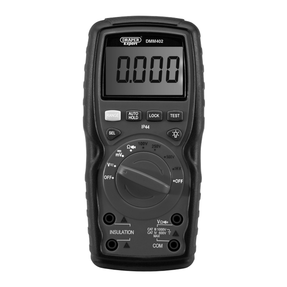
6. IDENTIFICATION LCD display window. Measurement function range switch. Function buttons. Probe sockets. -
Page 10: Function Buttons
6. IDENTIFICATION 6.1 FUNCTION BUTTONS - FIG. 1 FIG.1 RANGE Used to switch the meter between autorange mode and manual range mode as well as to select desired manual range. AUTO HOLD Used to enter or exit Display Hold mode or Auto Hold mode. LOCK. -
Page 11: Lcd
6. IDENTIFICATION 6.2 LCD - FIG. 2 Symbol Meaning Continuity test is selected. Diode test is selected. The meter is in Display Hold mode. The meter is in Auto Hold mode. Automatic power-off feature is enabled. The batteries are low and must be replaced immediately. -
Page 12: Unpacking & Checking
Carefully remove the product from the packaging and examine it for any sign of damage caused during shipping. Lay the contents out and check them. If any part is damaged or missing, do not attempt to use the tool and contact the Draper Helpline immediately (see back page for details). -
Page 13: Operating Instructions
8. OPERATING INSTRUCTIONS 8.1. MANUAL RANGING AND AUTORANGING The meter defaults to autorange mode when switched on. When the meter is in autorange mode, the symbol " " is displayed. 1. Press the RANGE button to enter the manual range mode, the symbol " "... -
Page 14: Measuring Dc Or Ac Voltage
8. OPERATING INSTRUCTIONS 8.3 MEASURING DC OR AC VOLTAGE 1. Connect the black test lead to the " COM " terminal and the red test lead to the " " terminal. 2. Set the measurement function range switch to the position. -
Page 15: Measuring Resistance
8. OPERATING INSTRUCTIONS 8.4. MEASURING RESISTANCE 1. Connect the black test lead to the " COM " terminal and the red test lead to the " " terminal. 2. Set the measurement function range switch to position. 3. Connect the test leads across the resistor to be tested. 4. -
Page 16: Continuity Test
8. OPERATING INSTRUCTIONS 8.5 CONTINUITY TEST 1. Connect the black test lead to the " COM " terminal and the red test lead to the " " terminal. 2. Set the measurement function range switch to position. 3. If the symbol " "... -
Page 17: Diode Test
8. OPERATING INSTRUCTIONS 8.6 DIODE TEST 1. Connect the black test lead to the " COM " terminal and the red test lead to the " " terminal. ( Note: The polarity of the red lead is positive " + ". ) 2. -
Page 18: Measuring Insulation Resistance
8. OPERATING INSTRUCTIONS 8.7 MEASURING INSULATION RESISTANCE IMPORTANT Turn off all power to the circuit to be tested and discharge all capacitors thoroughly before attempting insulation resistance test. Warning: 1. After you set the measurement function range switch in a test voltage position ("... -
Page 19: Auto Power Off
8. OPERATING INSTRUCTIONS 1. Connect the black test lead to a " INSULATION " terminal and the red test lead to the other " INSULATION " terminal. 2. Set the measurement function range switch to a desired test voltage position (" 100V ", "... -
Page 20: Maintenance
9. MAINTENANCE 9.1 BATTERY REPLACEMENT Before attempting to open the battery cover or case, make sure that the test leads have been disconnected from the meter. 1. If “ ”appears on the LCD display, it indicates that the battery should be replaced. 2. -
Page 21: Explanation Of Symbols
10. EXPLANATION OF SYMBOLS 10.1 EXPLANATION OF SYMBOLS WEEE Do not dispose of Waste Electrical Attention. & Electronic Equipment in with domestic rubbish High voltage / current! For indoor use. Danger. Do not expose to rain. Voltage AC Class II construction (Double insulated) Conforms to all relevant Voltage DC... -
Page 22: Disposal
11. DISPOSAL 11.1 DISPOSAL - At the end of the machine’s working life, or when it can no longer be repaired, ensure that it is disposed of according to national regulations. - Contact your local authority for details of collection schemes in your area. In all circumstances: •... - Page 23 NOTES...
- Page 24 ©Published by Draper Tools Limited. No part of this publication may be reproduced, stored in a retrieval system or transmitted in any form or by any means, electronic, mechanical photocopying, recording or otherwise without prior permission in writing from Draper Tools Ltd. DBMC0118...
Need help?
Do you have a question about the 400 Series and is the answer not in the manual?
Questions and answers