Table of Contents
Advertisement
Quick Links
Advertisement
Table of Contents

Related Manuals for Draper Expert 400 Series


Summary of Contents for Draper Expert 400 Series
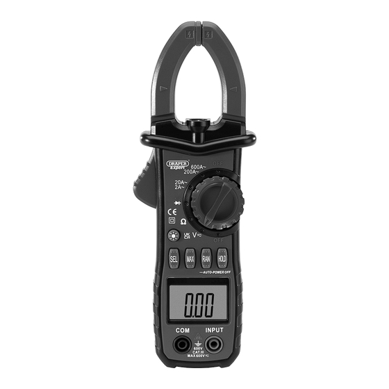
- Page 1 Original Instructions Version 3 June 2024 400 SERIES DIGITAL CLAMP METER 41864...
-
Page 2: Table Of Contents
Always use the latest version of Any other application beyond the conditions established for use the manual. Please visit drapertools.com/manuals for will be considered misuse. Draper Tools accepts no responsibility for improper use of this product. the latest version. - Page 3 DC Voltage Diode Range Accuracy Resolution Range Accuracy Resolution 200mV 0.1mV Displays the forward pressure drop approximation (Open circuit ±0.8% reading + 2 digits 10mV voltage of about 1.5V) 200V 0.1V 600V ±1% reading + 2 digits Overload protection: 250V DC or AC (RMS). Input impedance: 10MΩ.
-
Page 4: Health And Safety Information
− DO NOT use any other leads with this product than those supplied. Contact Draper Tools for • DO NOT operate this device with the rear housing replacement options if the leads become open or missing and DO NOT use it if the rear housing damaged. -
Page 5: Identification And Unpacking
Before assembling the product, lay the contents out and check them against the parts listed below. If any part is damaged or missing, do not attempt to use the product. Please contact the Draper Helpline; contact details can be found at the back of this manual. (9a) (9b) Measurement clamp head. -
Page 6: Operating Instructions
6. Operating Instructions 6.6 DC Voltage Measurement Important: Before operating this product, read and understand all the safety instructions listed in this 1. Rotate the measurement function selection dial to the manual. DC voltage position. 6.1 Back Light and Work Light Button 2. Connect the black lead to the COM probe socket (9a) and the red lead to the INPUT probe socket (9b). - Page 7 6. Operating Instructions 6.9 Continuity/Diode Test WARNING! Risk of electric shock. Make sure the circuit power is off, and the circuit capacitors are completely discharged. 1. Rotate the measuring function selection dial to the ) continuity position and ensure that the power to the circuit under test is off. 2.
-
Page 8: Maintenance And Disposal
Visit drapertools.com/warranty for more information. maintenance on this product. • Replace the probes IMMEDIATELY if they are damaged in any way or the conductors are exposed; contact Draper Tools for replacement options. Important: Replacement probes must be rated CAT III 20A. 7.1... -
Page 9: Explanation Of Symbols
9. Explanation of Symbols Read the instruction manual Fuse WEEE – Waste Electrical & Electronic Equipment Danger! High voltage/current Do not dispose of Waste Electrical & Electronic Equipment in with domestic rubbish For indoor use only; Voltage AC do not expose to rain Class II construction Voltage DC (Double insulated) - Page 10 Notes – 10 –...
- Page 11 Notes – 11 –...
- Page 12 Product Helpline: +44 (0) 23 8049 4344 Telephone Sales Desk: +44 (0) 23 8049 4333 General Enquiries: +44 (0) 23 8026 6355 Please contact the Draper Tools Product Helpline for repair and servicing enquiries. © Published by Draper Tools Limited © Published by Draper Tools Limited...
Need help?
Do you have a question about the Expert 400 Series and is the answer not in the manual?
Questions and answers