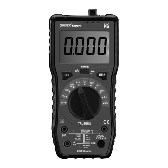
1. Preface 3. Product Introduction 1.1 Product Reference 3.1 Intended Use User Manual for: 400 Series Digital Multimeter This device is designed to measure voltage, current and resistance across AC and DC circuits. Fitted with a large LCD Stock No: 92433 backlit display screen, torch and an NCV (Non - contact voltage) sensor.
− DO NOT use any other leads with this product • Keep your fingers behind the guards on the probes than those supplied. Contact Draper Tools for during use. replacement options if the leads become • ALWAYS remove the contact leads from the device damaged.
Before assembling the product, lay the contents out and check them against the parts listed below. If any part is damaged or missing, do not attempt to use the product. Please contact the Draper Helpline; contact details can be found at the back of this manual. (7C)
6. Functions 6.1 LCD Display Explained 6.2 The Function Dial • Turn the function dial (6) and press the ‘’SEL’ button (5) to select the appropriate measurement type. 6.3 ‘SEL’ Select Button • The ‘SEL’ button (5) allows switching between the different test modes, switch temperature between Celsius and Fahrenheit, diode and continuity and frequency and duty cycle measurements.
7. Operating Instructions Important: Before operating this product, read and 3. Position the probe contacts across the source of the understand all the safety instructions listed in this circuit to be measured, observing the correct polarity. manual. 4. Enable the power to the circuit to be measured. The Important: Inspect the device for signs of damage, voltage value is displayed on the LCD screen (3).
Page 8
7. Operating Instructions 7.4 Resistance Measurement (Ω) • If the resistance is less than 50Ω the buzzer may sound. 1. If the resistance to be tested is part of a circuit, switch • If the test probes are open or the resistance measured the circuit off, disconnect the power and allow all is above 600Ω, ‘OL’...
Page 9
7. Operating Instructions 7.10 Transistor Testing Fig. 7 WARNING! DO NOT apply voltages above 36VDC or RMS to the ‘COM’ or ‘hFE’ terminals. 1. Turn the function dial (6) to ‘hFE’ position. 2. Determine whether the transistor is either type ‘NPN’ or ‘PNP’. Then insert the transistor pins into the corresponding ‘EBCE’...
• Replace the probes IMMEDIATELY if they are damaged in any way or the conductors are exposed; contact Draper Tools for replacement options. • Important: Replacement probes must be rated CAT III 1,000V (10A). • If the low battery indicator ( ) is shown on the display, replace the battery as soon as possible;...
10. Explanation of Symbols Read the instruction manual Fuse WEEE – Waste Electrical & Electronic Equipment Danger! High voltage/current Do not dispose of Waste Electrical & Electronic Equipment in with domestic rubbish For indoor use only; Voltage AC do not expose to rain Class II construction Voltage DC (Double insulated)
Need help?
Do you have a question about the 400 Series and is the answer not in the manual?
Questions and answers