
Related Manuals for Ingersoll-Rand IRIS-5GPM-V001


Summary of Contents for Ingersoll-Rand IRIS-5GPM-V001
- Page 1 IRIS-5GPM-IOM Revision A September 2024 Ingersoll Rand Ion Solutions IRIS-5GPM-V001 Installation, Operation and Maintenance Save These Instructions...
-
Page 2: Table Of Contents
4.14. Stainless Steel Y-Strainer ..................36 Page 2 IRIS-5GPM-V001 (en) - Page 3 5.9. SYSTEM LIGHT STATUS ................... . 53 IRIS-5GPM-V001 (en)
- Page 4 6.4. ACCESSORIES ....................65 Page 4 IRIS-5GPM-V001 (en)
- Page 5 IRIS-5GPM-V001 (en) Page 5...
-
Page 6: General Information
IRIS’ technology integrates seamlessly with existing systems, offering an easy-to-install, plug-and-play solution that delivers immediate value in a compact footprint. Control, enhance, and protect the future of your business and the planet with the natural genius of Ion Solutions. Page 6 IRIS-5GPM-V001 (en) -
Page 7: Unpacking
• Remove top box cover. • Remove foam insert. • Use handles to lift and remove IRIS from pallet. • Keep the system vertical. DO NOT lay the unit flat. Top Cover Foam insert Handle Foam insert Figure 1 IRIS-5GPM-V001 (en) Page 7... -
Page 8: Handling
Do not lift IRIS by the influent or effluent manifolds (figure 10, page 24) or by the attached IRISConnect box (figure 10). 1.5 NAME PLATE LABEL 1.6 IRIS SERVICES AND SUPPORT If problems cannot be solved with reference to the operating and maintenance instructions, please contact the manufacturer at iris-support@irco.com. Page 8 IRIS-5GPM-V001 (en) -
Page 9: Safety
(figure 10, page 24) or by the attached IRISConnect box (figure 10). IRIS system creates ozone along with other reactive oxygen species. Ozone can be harmful to human health in concentrations above OSHA permitted levels. IRIS-5GPM-V001 (en) Page 9... -
Page 10: Ozone Safety
Recommended - These materials are the most compatible with plasma activated water (PAW). Somewhat compatible - Materials may degrade under high concentration over extended contact. Not recommended - Materials will likely degrade. It is recommended to remove and replace with more compatible materials. Page 10 IRIS-5GPM-V001 (en) -
Page 11: Installation
6. Connect IRIS influent and effluent lines to external treatment tank. 7. IRIS influent and effluent lines should be plumbed in using flexible tubing to reduce stress on manifolds. • Provided hose barbs are meant for 1 inch ID flex tubing. IRIS-5GPM-V001 (en) Page 11... -
Page 12: Installation Requirements
5. Place the return line from IRIS as far as possible from the IRIS intake to minimize the chances of looping an isolated fraction of the total water supply. Tank end of return line from IRIS must be submerged in water at all times to reduce splashing of water. Excess splashing can release dissolved ozone gas. Page 12 IRIS-5GPM-V001 (en) -
Page 13: Mount Clearance
3.4.1 WALL MOUNT CLEARANCE 8.5” (215.9 mm) Minimum Clearance towards Top 55” (1397 mm) 8.5” 24“ (609.6 mm) 24“ (609.6 mm) 55” (1397mm) (215.9 mm) Minimum Clearance Minimum Clearance Minimum Clearance towards Right towards Right towards Bottom Figure 3 IRIS-5GPM-V001 (en) Page 13... -
Page 14: Floor Mount Clearance
3. INSTALLATION 3.4.2 FLOOR MOUNT CLEARANCE 8.5” (215.9 mm) Minimum Clearance towards Top 75” (1905 mm) 24“ (609.6 mm) 24“ (609.6 mm) 40” (1016 mm) Minimum Clearance Minimum Clearance towards Left towards Right Figure 4 Page 14 IRIS-5GPM-V001 (en) -
Page 15: Wall Mount Iris
NOTE: If the wall is not straight or the screws are not properly drilled in an even position, it can damage your product or cause risk of injury or death. WARNING Prior to installing the IRIS UNIT mount, read and comply with the instructions provided by the manufacturer. Take the necessary steps to ensure safe installation. IRIS-5GPM-V001 (en) Page 15... - Page 16 3. INSTALLATION See Detail A See Detail C See Detail B Detail A Detail B See Detail C Detail C See Detail D Detail D Figure 5 Page 16 IRIS-5GPM-V001 (en)
-
Page 17: Wall Mount Auxiliary Components
• The light tower will arrive laid on its side in the box. Remove the tape and place it on the light base, aligning with the guide arrows, then twist in a clockwise manner it into the locked position. IRIS-5GPM-V001 (en) Page 17... - Page 18 • The Oxygen flow controller will be pre-installed in the unit but may need adjustment. • Adjust the flow to achieve approximately 1.1 LPM. Due to the nature of an O2 sieve, the flow will oscillate. IRISConnect will provide the most accurate indicator of your average flow. Page 18 IRIS-5GPM-V001 (en)
- Page 19 3. INSTALLATION See Detail ‘A’ See Detail ‘B’ Detail ‘A’ Detail ‘B’ Figure 7 IRIS-5GPM-V001 (en) Page 19...
-
Page 20: Floor Mount Iris
NOTE: If the floor is not level or the concrete anchors are not properly secured, it can damage your product or cause risk of injury or death. WARNING Prior to installing the IRIS UNIT stand, read and comply with the instructions provided by the manufacturer. Take the necessary steps to ensure safe installation. Page 20 IRIS-5GPM-V001 (en) -
Page 21: Floor Mount Auxiliary Components
• Mount the Degas Vessel using the provided clamp, which will slide into the leg on the right side of the IRIS unit (detail A of figure 9). • Destruct • Mount the Destruct unit to the provided mounting plate using 1/4 in (6.35 mm) hardware. IRIS-5GPM-V001 (en) Page 21... - Page 22 • The Oxygen flow controller will be pre-installed in the unit but may need adjustment. • Adjust the flow to achieve approximately 1.1 LPM. Due to the nature of an O2 sieve, the flow will oscillate. IRISConnect will provide the most accurate indicator of your average flow. Page 22 IRIS-5GPM-V001 (en)
- Page 23 3. INSTALLATION See Detail ‘A’ Detail ‘A’ See Detail ‘A’ Detail ‘B’ Detail ‘A’ Detail ‘B’ Figure 9 IRIS-5GPM-V001 (en) Page 23...
-
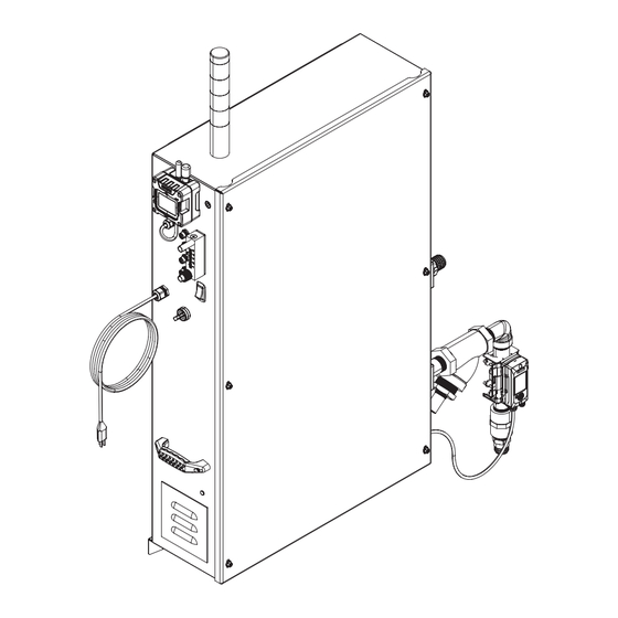
Page 24: Components Of The System
4. COMPONENTS OF THE SYSTEM 4.1 OVERVIEW Figure 10 Page 24 IRIS-5GPM-V001 (en) - Page 25 Controls all aspects of IRIS unit by receiving inputs from customer setpoints or sensor feedback and using this information to adjust IRIS controls to meet specific targets. Steps up (increases) power received from the PCB and sends it to the plasma chamber Transformer for plasma generation. IRIS-5GPM-V001 (en) Page 25...
-
Page 26: Ati Ozone Leak Detector
The sensor is inserted into the housing at the base of the transmitter. They are easily removed, and installation is simplified by way of an indexing groove that aligns the connector for perfect fit. Once installed, a threaded port cap secures it in place. Page 26 IRIS-5GPM-V001 (en) -
Page 27: Degas Vessel
MDV should be mounted within 2-3 feet of the IRIS outlet. The vent line should be connected to the ozone destruct, and the ozone destruct should be mounted near the ATI ozone sensor. Install provide Unistrut then bolt degas vessel to Unistrut with provided clamp. IRIS-5GPM-V001 (en) Page 27... -
Page 28: Cdu Ozone Destruct
A water trap can be added as an option to remove bulk moisture. This is recommended for off-gas situations where a common air vent is used for off-gassing. Large quantities of water can be safely drained with the water trap. Page 28 IRIS-5GPM-V001 (en) -
Page 29: Plasma Chamber
NOTE: When completing maintenance on the ORP probe, always disconnect ORP probe connection from IRIS box to prevent wire from twisting. Ensure that ORP probe wire is not twisted or bent as this could result in the wire breaking which would permanently damage your ORP probe. IRIS-5GPM-V001 (en) Page 29... -
Page 30: Keyence Flow Sensor
The measured flow rate value is relayed directly to the IRIS controls to ensure a stable water flow to the plasma chamber as well as faulting if there is too much or too little flow in the system. Page 30 IRIS-5GPM-V001 (en) -
Page 31: Flomax® 75 Pump
Provision for a priming plug can be made by using a close nipple and tee on the discharge opening. A pipe plug installed in the top opening of the tee is easily removed when necessary to prime pump. Prime pump by filling pump housing with liquid. IRIS-5GPM-V001 (en) Page 31... -
Page 32: Compressor
• Energy costs are minimized because there’s no need to increase force - some fluid-flooded units can see a downstream pressure drop due to filtration. • Reduced oil costs, because there’s no need to continually refill your compressor. Page 32 IRIS-5GPM-V001 (en) -
Page 33: Oxygen Concentrator
The oxygen concentrator is a device that concentrates the oxygen from ambient air by first removing humidity and then selectively removing nitrogen to supply an oxygen - enriched gas stream. It is used to provide oxygen to the plasma chamber. It includes a water dump valve programmed to drain at a routine time. IRIS-5GPM-V001 (en) Page 33... -
Page 34: Light Tower
Unit is ready in standby Blinking Solid Machine running, plasma off Solid Machine running, plasma on Solid Machine Fault Safety Faults - Ozone or reactor safety Solid event Solid Blinking Solid Reactor Control Safety - Water Circulation Page 34 IRIS-5GPM-V001 (en) -
Page 35: Irisconnect
The system allows owners to review historic data in tabular or graph formats, receive status notifications and system updates, and monitor system run time for maintenance. Users can also download weekly performance reports and enhance their IRIS operation with ease and efficiency. Figure 21 IRIS-5GPM-V001 (en) Page 35... -
Page 36: Stainless Steel Y-Strainer
4. COMPONENTS OF THE SYSTEM 4.14. Stainless Steel Y-Strainer The stainless-steel Y-Strainer is used to filter any contaminates to prevent them from reaching the IRIS plasma chamber. Figure 22 Page 36 IRIS-5GPM-V001 (en) -
Page 37: System Operation
Measuring the inlet ORP will provide a measurement of the water in the entire tank rather than the water exiting the plasma chamber. See section 5.4 for more details and why to choose one run mode over another type. IRIS-5GPM-V001 (en) Page 37... -
Page 38: Operation Overview
• Remove the priming plug and fill the pump to the top with reverse osmosis water. • Once the pump is full of water, replace the priming plug and front cover of the IRIS unit. • Ensure front cover is replaced and secure after priming before re-energizing the system. Page 38 IRIS-5GPM-V001 (en) - Page 39 5. SYSTEM OPERATION Removing Front Cover Removing Priming plug Replacing the Priming cap and Front cover Figure 24 IRIS-5GPM-V001 (en) Page 39...
-
Page 40: Run Modes
20V – 35V. Operating below 20V primarily provides oxygenation only. 25V – approximately 0.3 PPM of DO3 is generated on RO water at 69.8° F (21°C) 35V – approximately 1.0 PPM of DO3 is generated on RO water at 69.8° F (21°C) Page 40 IRIS-5GPM-V001 (en) -
Page 41: Water Circulation Mode
This mode is used to circulate water through the system while plasma is off. Reactive Oxygen Species (ROS) are produced when plasma is on and operational. It is recommended to operate in Water Circulation Mode during startup and when troubleshooting IRIS to eliminate the risk of releasing ozone gas. IRIS-5GPM-V001 (en) Page 41... -
Page 42: Default Operation
IRISConnect works on a cellular network, and it must send the update command and receive the reading. This is not instantaneous. Refrain from pressing the update button repeatedly as this can cause communication lockups. If this occurs, close out your IRISConnect browser and open it again. This will generally get past the communication issues. Page 42 IRIS-5GPM-V001 (en) -
Page 43: Water Circulation And Flow Setup
Verify the system is still setup in Water Circulation Mode then turn the unit on. Run Switch START PHYSICAL SWITCH SETTINGS Power Switch Plasma Setting Plasma OFF REMOTE SWITCH SETTINGS Operational Run Mode AUTO ORP (Default setting) Run Switch Power Switch Figure 26 IRIS-5GPM-V001 (en) Page 43... -
Page 44: Keyence Flow Sensor Setup
Select ‘Set’ when “The history will be deleted” prompt is displayed. Connected Sensors: ITEM SETTING Flow Port FD-H32 Multi-port 1 ---- Multi-port 2 ---- Select ‘Set’ Initial Settings (Sensor): ITEM SETTING Flow Direction Pipe Size 1” Pipe Material Metal Select “Set and Continue” Page 44 IRIS-5GPM-V001 (en) - Page 45 If flow rate does not stabilize at 5 GPM refer to the Trouble Shooting Section. Figure 27 Check the external piping and plumbing for water leaks. IRIS-5GPM-V001 (en) Page 45...
-
Page 46: Stopping Instructions
READY state (indicated by solid YELLOW and GREEN), the system may be powered off or switched back on to generate plasma. WARNING: It is recommended to wait for unit to indicate READY state before attempting to run unit again or shutting off power, to avoid unexpected behaviors. Page 46 IRIS-5GPM-V001 (en) -
Page 47: Remote Operation (Irisconnect)
30 seconds for screen to be updated with the latest information from the unit. IRISConnect will update once a minute when the system is running, or 20 minutes when idle. IRIS-5GPM-V001 (en) Page 47... -
Page 48: Page Overview Navigation
ON position, and the run switch is in the START position, which is indicated by the SWITCH STATUS LED, directly below the START STOP buttons. If the physical run switch is not in the START position, these buttons will be greyed out. Page 48 IRIS-5GPM-V001 (en) -
Page 49: Led Status Light Indicators
Voltage Setpoint can only be changed if the system is in Voltage mode. Voltage inputs can be entered between 8 and 35 volts ORP Setpoint can only be changed if the system is in AUTO ORP mode. ORP targets can be set between 50 mV and 1150 mV. IRIS-5GPM-V001 (en) Page 49... -
Page 50: Update Button
O2 Flow read out provides a quick glance of the current oxygen flow rate. This is useful if adjustments need to be made. 5.8.10 READINGS GRAPH Data extraction: Customers have the option to extract their data in a graphical or tabular manner within a specified date range for data analysis purposes. Page 50 IRIS-5GPM-V001 (en) -
Page 51: Status Log
The LED status section to the right of the log gives an overall look at which component has a status or fault. 5.8.12 CONFIGURATION This page allows the settings for Auto ORP to be updated for the application. IRIS-5GPM-V001 (en) Page 51... -
Page 52: Unit Information
This report is exportable to multiple formats. SMS Report This report will log SMS/Text messages sent to the mobile number of the users assigned to receive alerts from the device. This report is exportable to multiple formats. Page 52 IRIS-5GPM-V001 (en) -
Page 53: System Light Status
Unit is ready in standby Blinking Solid Machine running, plasma off Solid Machine running, plasma on Solid Machine Fault Solid Safety Faults - Ozone or reactor safety event Solid Blinking Solid Reactor Control Safety - Water Circulation IRIS-5GPM-V001 (en) Page 53... -
Page 54: Maintenance And Troubleshooting
• Calibration frequency is based on application and system design. It is recommended that the onboard ORP probe be calibrated quarterly in RO applications. Refer to supplemental document for ORP probe calibration on the Ion Solutions resource page at: https://www.ingersollrand.com/en-us/ion-solutions/resources. Page 54 IRIS-5GPM-V001 (en) -
Page 55: Y Strainer Filter
• Place new concentrator on mounting studs and ensure no wires or hoses are between concentrator backplane and IRIS main box. • Place nuts back on 4 mounting studs and secure until tight. • Reconnect influent air hose from compressor and effluent air hose from concentrator. • Reconnect wiring harness to oxygen concentrator. IRIS-5GPM-V001 (en) Page 55... -
Page 56: Ozone Destruct
• Dispose of carulite following local statutory guidelines. • Fill ozone destruct with fresh carulite media. • Thread previously removed fitting back into the top of the ozone destruct. • Re-install ozone destruct onto IRIS unit following installation guidelines. Page 56 IRIS-5GPM-V001 (en) -
Page 57: Ati Ozone Leak Detector
• It is recommended that the ATI ozone leak detector sensor is replaced yearly. NOTE: The ATI ozone sensors have a shelf life of 9 months. Avoid purchasing excessive numbers of this component to avoid waste. GAS TRANSMITTER Sensor Housing Sensor Sensor Cap Figure 31 IRIS-5GPM-V001 (en) Page 57... -
Page 58: Air Compressor
NOTE: There are air vents on the top right and lower left sides of the unit. These vents must remain free of debris. Check vents for obstructions on a monthly basis. If obstructions are seen use a compressor to clean vents. This will ensure proper air flow through IRIS unit. Page 58 IRIS-5GPM-V001 (en) -
Page 59: Pump Seals
6. MAINTENANCE AND TROUBLESHOOTING 6.2.7 PUMP SEALS • Mechanical seal • Face seal See Detail ‘A’ Mechanical seal Face seal Detail ‘A’ Figure 33 IRIS-5GPM-V001 (en) Page 59... - Page 60 • Install the new face seal with the reused washer onto the pump housing. • Place the face plate back on the pump and torque the bolts to 60 - 80 in-lb (6.7 - 9.03 N·m). Page 60 IRIS-5GPM-V001 (en)
- Page 61 Contact support Reactor Control Safety Contact support Shutdown Status indicating the ORP reading is above the normal reading System ORP Reading range for the IRIS unit. You may confirm reading with an Above Range external probe. IRIS-5GPM-V001 (en) Page 61...
- Page 62 Using the power switch, turn Communication Error the unit off and wait 5 minutes before switching the unit back on. If this does not resolve the status, contact support. System Ambient Ozone Contact support. Shutdown Page 62 IRIS-5GPM-V001 (en)
-
Page 63: Status Code And Communication Guide
• Check the oxygen flow valve, which is on the left panel. While the air compressor is running, adjust the knob until the flow rate is reading about 1.1 LPM. When the flow rate gets close to the 1.1 LPM target flow rate, the pump motor should kick on. IRIS-5GPM-V001 (en) Page 63... - Page 64 Keyence flow meter is installed on, but no values or - appears on the display, repeat the Keyence flow meter installation and setup in section 5.6.5. Pay particular attention to the recommended torque requirements when installing the flow meter in the Keyence installation guide. Page 64 IRIS-5GPM-V001 (en)
-
Page 65: Accessories
If this carrier does not provide sufficient service in your area and you are experiencing connectivity issues, please reach out to iris-support@irco.com for additional options. • IRIS stand • IRIS stand is sold separately from IRIS unit. Refer to section 3.6 for floor mounting instructions using IRIS stand. IRIS-5GPM-V001 (en) Page 65... - Page 66 Page 66 IRIS-5GPM-V001 (en)
- Page 67 IRIS-5GPM-V001 (en) Page 67...
- Page 68 About Ingersoll Rand Ingersoll Rand Inc. (NYSE:IR), driven by an entrepreneurial spirit and ownership mindset, is dedicated to helping make life better for our employees, customers and communities. Customers lean on us for our technology-driven excellence in mis- sion-critical flow creation and industrial solutions across 40+ respected brands where our products and services excel in the most complex and harsh conditions. Our employees develop customers for life through their daily commitment to expertise, productivity and efficiency.
Need help?
Do you have a question about the IRIS-5GPM-V001 and is the answer not in the manual?
Questions and answers