Table of Contents
Advertisement
Quick Links
Instructions
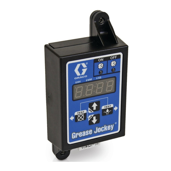
Grease Jockey
Lubrication Controller
For controlling and monitoring an automated lubrication system.
Not approved for outdoor use or use in explosive atmospheres or hazardous locations.
Model: 24W482
Important Safety Instructions
Read all warnings and instructions in this
manual. Save these instructions.
334662B
EN
Advertisement
Table of Contents

Related Manuals for Graco 24W482


Summary of Contents for Graco 24W482
- Page 1 Lubrication Controller 334662B For controlling and monitoring an automated lubrication system. Not approved for outdoor use or use in explosive atmospheres or hazardous locations. Model: 24W482 Important Safety Instructions Read all warnings and instructions in this manual. Save these instructions.
- Page 2 Warnings Warnings The following warnings are for the setup, use, grounding, maintenance, and repair of this equipment. The exclama- tion point symbol alerts you to a general warning and the hazard symbols refer to procedure-specific risks. When these symbols appear in the body of this manual or on warning labels, refer back to these Warnings. Product-specific hazard symbols and warnings not covered in this section may appear throughout the body of this manual where applicable.
-
Page 3: Component Identification
Component Identification Component Identification Keypad, Display, and Icons RIGHT Direction Arrow / TEST / ENTER (D) NOTICE • In SETUP MODE, saves entry, moves cursor in To prevent damage to soft key buttons, do not press display one field to the right or to the next setup the buttons with sharp objects such as pens, plastic step. -
Page 4: Installation
Installation Installation The installation shown in F . 2 is only a guide for selecting and installing system components. Contact your Graco distributor for assistance in planning a system to suit your needs. Pump Timer Mating Harness Wiring Harness Black... -
Page 5: System Wiring
1. Connect timer leads to solenoid. A wiring harness 3. Connect the black lead wire to the chassis ground. kit with a mating connector is available from your Graco distributor. Installing the Lubrication Controller 1. Select a flat surface to install the Lubrication Con- troller. - Page 6 Setting Up a Personal Identification Number (PIN) (Optional) Setting Up a Personal Identification Number (PIN) (Optional) Setup Code A1 is available to secure the setup modes with a PIN. A required PIN provides the system with added security by preventing unauthorized users from making adjustments to the settings. A PIN is not required. Entering a PIN Code for the First Time Entering Advanced Setup Press the UP ARROW button for 3 sec-...
- Page 7 Setup Setup Entering SETUP MODE Time Control (on:ti) ON Setup 1. on:ti is on the display. Press both the UP and DOWN ARROW buttons together for three seconds. If the Grease Jockey Controller was previously set up to 2. Press ENTER. require a PIN Code: a.
- Page 8 Setup Programming OFF TIME Duration • The highest number that can be set for the MM field value is 59. After setting the parameters for the Time (Ti) ON Mode, the OFF TIME or PUMP REST CYCLE must be set up. 5.
-
Page 9: Operation
Setup Operation Run Mode Test Mode The controller is in Run Mode providing the following cir- To enter Test Mode: cumstances are present: 1. Press the LEFT and • The controller is not in SETUP MODE. RIGHT ARROW buttons together for •... -
Page 10: Troubleshooting
Replace fuse. If fuse trips again, con- tact Graco Customer Support. Incorrect or loose wiring Confirm current is being delivered to the pump during pump ON. Refer to installation instructions, page 4. - Page 11 Parts Parts Ref. Description BOX, enclosure LABEL, control, overlay LABEL, serial, name LABEL, connector Accessories Related Kits Kit No. Description 127900 HARNESS, Grease Jockey, Delphi 280 127899 HARNESS, Grease Jockey, Delphi 56 24P314 CABLE, wiring harness 17C942 BRACKET, timer 334662B...
-
Page 12: Technical Data
Technical Data Technical Data Input Contact Power Source DC 9 - 32 VDC Power Consumption 1 Watt Outputs Pump control Pump Control Voltage = Power Source Voltage Pump Control Voltage = Power Source Max Switching Voltage 32 VDC Max Switching Current 9A (DC) Min Switching Current 100 mA (DC) -
Page 13: Mounting Hole Layout
Dimensions Dimensions Mounting Hole Layout Ø 0.2 in. (5.0 mm)- 4.92 in. (125.0 mm) 2.75 in. (70.0 mm) 1.38 in. (35.0 mm) 1.57 in. (40.0 mm) 5.53 in. (140.0 mm) 334662B... -
Page 14: Graco Standard Warranty
With the exception of any special, extended, or limited warranty published by Graco, Graco will, for a period of twelve months from the date of sale, repair or replace any part of the equipment determined by Graco to be defective.
Need help?
Do you have a question about the 24W482 and is the answer not in the manual?
Questions and answers