Sign In
Upload
Download
Table of Contents
Contents
Add to my manuals
Delete from my manuals
Share
URL of this page:
HTML Link:
Bookmark this page
Add
Manual will be automatically added to "My Manuals"
Print this page
×
Bookmark added
×
Added to my manuals
Manuals
Brands
Autoscript Manuals
Camera Accessories
TallyPlus
User manual
Autoscript TallyPlus User Manual
On-camera prompter accessories
Hide thumbs
1
2
Table Of Contents
3
4
5
6
7
8
9
10
11
12
13
14
15
16
17
18
19
20
21
22
23
24
25
26
27
28
29
30
31
32
33
page
of
33
Go
/
33
Contents
Table of Contents
Troubleshooting
Bookmarks
Table of Contents
Table of Contents
Safety
About this Manual
Components and Connections
Installation
Mounting the Tally Opto Sensor
Mounting the Tallyplus
Mounting the Clockplus
Tally Connections
Power Connections
Timecode Connections (Clockplus)
Configuration
Adjusting the Opto Sensor Sensitivity (Tallyplus and Clockplus)
Adjusting the Display Brightness (Tallyplus and Clockplus)
Changing the Camera Number (Tallyplus)
Changing the Clock Display Format (Clockplus)
Timecode Selection (Clockplus)
Operation
Tally Function Operation (Tallyplus and Clockplus)
Timecode Operation (Clockplus)
Maintenance
Troubleshooting
Technical Specification
General Notices
Advertisement
Quick Links
1
Mounting the Tally Opto Sensor
2
Tally Connections
Download this manual
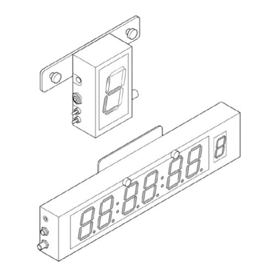
TallyPlus
ClockPlus
On-Camera Prompter
Accessories
Part Nos. TALLYPLUS
CLOCKPLUS
www.autoscript.tv
EN
Table of
Contents
Previous
Page
Next
Page
1
2
3
4
5
Advertisement
Table of Contents
Need help?
Do you have a question about the TallyPlus and is the answer not in the manual?
Ask a question
Questions and answers
Subscribe to Our Youtube Channel
Related Manuals for Autoscript TallyPlus
Camera Accessories Autoscript ClockPlus User Manual
On-camera prompter accessories (33 pages)
Camera Accessories Autoscript E.P.I.C. 17 Inch TFT User Manual
On-camera prompter (41 pages)
This manual is also suitable for:
Clockplus
Table of Contents
Print
Rename the bookmark
Delete bookmark?
Delete from my manuals?
Login
Sign In
OR
Sign in with Facebook
Sign in with Google
Upload manual
Upload from disk
Upload from URL


Need help?
Do you have a question about the TallyPlus and is the answer not in the manual?
Questions and answers