
Subscribe to Our Youtube Channel
Related Manuals for Autoscript E.P.I.C. 17 Inch TFT

Summary of Contents for Autoscript E.P.I.C. 17 Inch TFT
- Page 1 E.P.I.C. 17 Inch TFT On-Camera Prompter Part No. EPIC17-ME EPIC17-SDI-ME www.autoscript.tv...
- Page 2 Copyright © 2014 All rights reserved. Original Instructions: English All rights reserved throughout the world. No part of this document may be stored in a retrieval system, transmitted, copied or reproduced in any way, including, but not limited to, photocopy, photograph, magnetic or other record without the prior agreement and permission in writing of the Vitec Group plc.
-
Page 3: Table Of Contents
Contents Safety..........2 Fitting the Reflective Glass Panel . -
Page 4: Safety
Intended Use CAUTION! Only use the power cable specified for this The E.P.I.C. 17 Inch TFT high brightness on-camera prompter has product and certified for the country of use. been designed to provide a high quality teleprompting facility for television broadcasting. -
Page 5: About This Manual
Safety and About this Manual Basic Electrical Insulation (Class 1 equipment) Operating Environment WARNING! This product is Class 1 equipment. For safe CAUTION! The product should not be used outside the operation this equipment must be connected to a power operating temperature limits. -
Page 6: Components And Connections
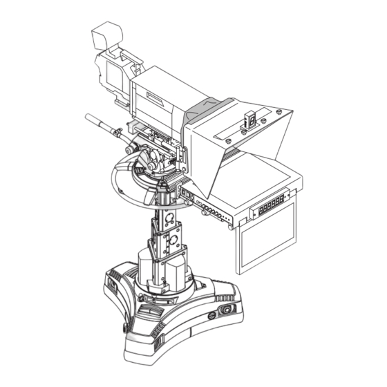
Components and Connections On-Camera Prompter Key Components The illustration below highlights the key components used in a typical prompter installation. Camera mounting plate Counterbalance weights Light shield TallyPlus Hood Reflective glass E.P.I.C. TFT monitor ClockPlus-E Monitor mounting brackets Main prompter mounting extrusion Hood mounting brackets... -
Page 7: Prompter Installation Components
Components and Connections Prompter Installation Components Prompter Mounting Components The following section describes the range of component parts available for a complete prompter installation using the E.P.I.C TFT monitor. Many of the parts listed are optional, depending on the specific requirements of the installation. - Page 8 Components and Connections Hood Components Clock & Tally Components Part Description Part Description MH-W Moulded hood, wide ClockPlus-E Clock/tally light LIGHTSHIELD-L Light shield cloth, Large TallyPlus Tally light RGMH-W Reflective glass...
-
Page 9: Box Contents
Components and Connections Tools Required Box Contents Metric Allen key set. Part Description EPIC17-ME 17” LED TFT Prompter Monitor EPIC17-SDI2-ME 17” LED TFT Prompter Monitor with HD/SDI installed... -
Page 10: Prompter Monitor Connections
Components and Connections Prompter Monitor Connections Prompter Monitor Control Panel AC power socket (IEC) Fuse holder Power switch Prompter power status LED DC power socket (4 pin XLR) Prompter screen selection button HD-SDI 2 IN and OUT sockets Video input selection button CVBS IN socket Onscreen set up button CVBS OUT socket... -
Page 11: Installation
Installation Mounting the Camera and Extrusion Screw the telescopic rods (TR7 or 12) into the mounting holes on the front of the camera head support. WARNING! Before attempting to install or adjust the prompter assembly, the tilt axis of the head support must be securely locked horizontally (tilt axis). -
Page 12: Mt-Black Mounting Plate
Installation MT-BLACK Mounting Plate Fit the MT-BLACK mounting plate to the camera support. Fit the camera head support plate to the base of the MT-BLACK mounting plate. Fit the mounting plate for the camera being used to the top of the MT-BLACK mounting plate, using the fixing screws provided. -
Page 13: Mounting The Extrusion
Installation Screw the telescopic rods (TR5, 7 or 12) into the mounting blocks Remove the two protective end caps from the extrusion. on the MT-BLACK mounting plate. Observing the correct orientation, slide the extrusion over the end clamps on the telescopic rods.. Mounting the Extrusion Unscrew the twist locks on the telescopic rods to loosen the extension sections. -
Page 14: Mounting The Prompter Monitor
Installation Centralise the extrusion, aligning the marker with the centre of the Mounting the Prompter Monitor camera lens. WARNING! Before attempting to install or adjust the prompter monitor assembly, the tilt axis of the head support must remain securely locked horizontally. WARNING! The prompter monitor must be isolated from the AC power supply during installation or adjustment. - Page 15 Installation With the rod mounting screws loosened, slide the monitor rods With the monitor supported, carefully slide the end clamps of the through the rod mountings in the base of the prompter monitor. prompter monitor rods into the slot on the front of the extrusion. Ensure that the indents on the end clamps are correctly seated on the extrusion.
-
Page 16: Assembling And Fitting The Hoods
Installation Assembling and Fitting the Hoods Centralise the prompter monitor with the marker on the extrusion. Secure the monitor in position by tightening the clamping screw. A range of hoods are available for use with the E.P.I.C. on-camera prompter. The hoods are available in solid moulded or folding versions, in various sizes, to suit the camera and monitor being used in the installation. -
Page 17: Folding Hoods - Initial Assembly
Installation Folding Hoods - Initial Assembly Fold the side flags outwards. The hoods are supplied flat-packed and require some basic assembly. When used for outside broadcast and other portable applications, the Align the two eyelets in the top flag with the tabs and twist to lock. hoods can easily be folded flat again for transportation. -
Page 18: Assembling The Extra Wide Folding Hood
Installation Assembling the Extra Wide Folding Hood Align the single eyelets in both the side flags with the tabs and twist to lock. Align the holes in the prompter and angle brackets with the two threaded holes in the mounting plate. Tighten the fixing screws to secure the whole bracket assembly. -
Page 19: Fitting The Hoods
Installation Fitting the Hoods Fitting the Extra Wide Folding Hood Align the clamps on the ends of the hood brackets with the slot in When the hood has been assembled, it can be installed onto the the top of the extrusion. Slide the hood assembly onto the prompter assembly. -
Page 20: Fitting The Extrusion End Caps
Installation Fitting the Extrusion End Caps Adjust the vertical position of the hood to centralise it with the camera lens and fully re-tighten the clamp screws. WARNING! When the hood has been installed, the supplied extrusion end caps must be fitted to protect against Adjusting the Prompter Assembly Position personal injury. -
Page 21: Fitting The Reflective Glass Panel
Installation Fitting the Reflective Glass Panel Fitting the Glass Panel The installation procedure for the glass panel is the same on all types WARNING! Risk of personal injury or injury to others. of hood, although there are more fixing screws on the larger hoods. Care must be taken when handling and installing the Remove all the fixing reflective glass panels. - Page 22 Installation With the glass supported at all times, replace the top glazing bar and secure with the fixing screws.
-
Page 23: Fitting The Tallyplus
Installation Fitting the TallyPlus Fit the TallyPlus to the hood, aligning the fixing holes in the brackets and securing with the two fixing screws provided. Fit the mounting bracket to the rear of the TallyPlus using the two fixing screws provided. The mounting bracket can be fitted to the lower set of mounting holes to increase the height of the TallyPlus above the hood. -
Page 24: Fitting The Clockplus-E
Installation Fitting the ClockPlus-E Align the ClockPlus-E connector with the interface connector on the monitor. Fit the the ClockPlus-E to the monitor. WARNING! Before attempting to install or adjust accessories, the tilt axis of the head support must be securely locked horizontally (tilt axis). The Tally Light cover must be removed before fitting the ClockPlus-E Remove the four fixing screws from the Tally Light cover. -
Page 25: Adjusting The Talent Monitor
Installation Adjusting the Talent Monitor Allow the talent monitor to swing down vertical. Position as desired and tighten the clamp to secure in place. Loosen the clamp on the side of talent monitor. The talent monitor can be left unlocked to allow it to remain vertical when the camera support is tilted up or down. -
Page 26: Fitting The Light Shield Cloth
Installation Fitting the Light Shield Cloth Fitting the Counterbalance Weights The prompter installation must have counterbalance weights fitted to CAUTION! Ensure that the light shield cloth is only loosely the rear of the mounting to compensate for the front-heavy effect of the fitted around the body of the servo lens to allow it to prompter monitor and hood. -
Page 27: Balancing And Adjustments
Installation Balancing and Adjustments If the payload is not correctly balanced, lock the tilt axis and: a) If the payload is falling forward (front heavy), move the WARNING! After fitting or adjusting the prompter assembly counterbalance weights further back on the rods. and any accessories, the payload must be correctly re- balanced. - Page 28 Installation Additional Adjustments WARNING! Before attempting to adjust the positions of the WARNING! Before attempting to adjust the prompter mounting blocks on the camera plate, the counterbalance assembly, the tilt axis of the head support must be securely weights and prompter assembly must be removed. locked horizontally (tilt axis).
-
Page 29: Connecting The Prompter Monitor
Installation Connecting the Prompter Monitor CVBS Connection Video Connections Connect the video signal (for prompter display) using one of the following options. Connection using composite video or HD/SDI to the prompter monitor should always be made with screened 75Ω coaxial cable.The video cable screen should be connected to earth (ground) at both ends. - Page 30 Provides a 12V DC supply to operate external accessories such as the Autoscript TallyPlus. Tally Light Repeat Connection Provides connection for an Autoscript tally device such as the TallyPlus to relay the tally indication signal being used by the monitor. For more information on the specifications of the accessory sockets,...
-
Page 31: Powering Up
Installation Power Connections Powering Up The prompter monitor can be powered by either an AC supply or a Before powering up, ensure that all external cable connections have 12VDC supply. been secured correctly. AC Power Connection To power up, operate the on/off rocker switch. WARNING! This product is Class 1 equipment. -
Page 32: Configuration
Configuration Control Panel Buttons Prompter Button The buttons on the control panel are used to configure the setup of the Button Button Function Colour Status prompter monitor screen. The buttons have legends to indicate their PROMPTER button allows When display function, and are back-illuminated. -
Page 33: User Monitor Setup Menus
Configuration Menu Buttons The control range of some parameters is limited intentionally to prevent erratic operation. This group of five buttons are for on-screen menu navigation. The menus are accessed by pressing the SETUP key, and navigated Button Button Function using the MENU and four ARROW keys. -
Page 34: Remote Control Configuration Setup Menu
Configuration Remote Control Configuration Setup Menu Sub Menus Parameters Description The E.P.I.C. TFT monitors are shipped with the Remote Control System Setup Menu - Switch Brightness Menu (Cont.) configuration socket blanked as standard. However, this can be included as an optional extra on request. When installed, the Remote Dimmed setting 0 - 31 Provides control over the dim... -
Page 35: Maintenance
Maintenance Routine Maintenance No solvents or glass cleaners should be used. Only use clean water and a damp lens cloth when cleaning. Do not apply excessive pressure The E.P.I.C. TFT on-camera prompters requires minimal routine to the reflective glass panel during the cleaning process. maintenance, apart from checking the connections and overall operation periodically. -
Page 36: Troubleshooting
Troubleshooting Fault Check Comments The monitor is not Check that the AC power source is connected and secured. See the section Powering Up on page 29 powering up. Check that the DC power source is connected and secured. Check that AC power is being supplied to the DC adaptor. Check the fuse and replace if necessary. -
Page 37: Technical Specification
Technical Specification Prompter Physical Data Prompter Display Data Brightness ........1600 nits 47.5 cm (18.75 in.) Width* Aspect ratio . - Page 38 GROUND Provides a 12V DC supply to operate external accessories such as the Connection for an external Autoscript opto sensor to activate the built- Autoscript +Tally-Plus+. Fused internally with a resettable fuse. in tally light on the monitor. The sensor is attached to the camera tally LTC Input light and allows the monitor to mimic the operation of the camera tally.
-
Page 39: General Notices
General Notices FCC Certification Declaration of Conformity E.P.I.C. Prompter EPIC17 EPIC 17-SDI Vitec Videocom Limited declares that this product has been FCC Notice manufactured in accordance with BS EN ISO 9001:2008. This product complies with the limits for a Class A digital device, This product complies with the following EU Directives: pursuant to Part 15 of the FCC Rules. - Page 40 General Notices European Union Waste of Electrical and Electronic Equipment (WEEE) Directive (2002/96/EC) This symbol marked on the product or its packaging indicates that this product must not be disposed of with general household waste. In some countries or European Community regions separate collection systems have been set up to handle the recycling of electrical and electronic waste products.
- Page 41 Publication part No. EPIC17-4980/1 Autoscript www.autoscript.tv itec Group brand...
Need help?
Do you have a question about the E.P.I.C. 17 Inch TFT and is the answer not in the manual?
Questions and answers