Advertisement
READ CAREFULLY AND FOLLOW ALL INSTRUCTIONS FOR YOUR OWN SAFETY
• DISCONNECT AC POWER SUPPLY BEFORE SERVICING.
• BASIC SAFETY PERCAUTIONS SHOULD ALWAYS BE FOLLOWED TO REDUCE THE RISK OF FIRE,
ELECTRICAL SHOCK, PERSONAL INJURY AND PRODUCT DAMAGE.
• Installation and servicing of this equipment should be performed by qualified service personnel only.
• Ensure the electricity connections conform to the National Electrical Code and local regulations if applicable.
• Do not mount near gas or electrical heaters.
• Equipment should be mounted in locations and at heights where it will not readily be subjected to tampering by
unauthorized personnel.
• The use of accessory equipment not recommended by the manufacturer may cause an unsafe condition. Any
modification or use of non-original components will void the warranty and product liability.
• Do not use this equipment for other than intended use.
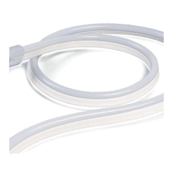
The specialtyLED Flexible Border Tube Color Jacket is a unique product made up of Light Emitting Diodes (LED)
consecutively connected in a flexible PVC housing. Due to the nature of the product special care is required during the
installation process to protect the internal wiring.
SAFETY PRECAUTIONS:
• All connector joints must be installed correctly to achieve IP68 rating.
• Do not over extend the minimum concave bend radius of 4.724 inches. When installing in the mounting channels or
Mounting clips it is easy to bend the product back and exceed 4.724 inches without noticing.
• Do not cover the product unless done so with extreme caution and attention to ventilation.
• Do not apply power when tightly coiled. Maintain half inch spacing between parts.
• Do not puncture, cut, shorten or splice outside of the designated cutting marks.
• Do not route through walls, doors, windows or building structures.
• Do not mount inside cabinets, tanks or enclosures unless properly ventilated.
• Do not unroll on a rough surface or over sharp corners. This will scratch the PVC optics.
• When unrolling or installing do not twist, pull or kink the product.
• Do not operate if outer jacket is damaged or there are loose connections. Inspect periodically for damage.
• Do not secure with staples, nails or like means that can damage the insulated PVC housing.
• Do not install in locations where it is subject to continuous flexing.
• Do not operate in temperatures exceeding 113°F (45°C).
• Ground Fault Circuit Interrupter (GFCI) protection should be provided on all circuits when used for outside
applications.
• Do not operate on circuits that do not have proper surge suppression protection. High voltage spikes will
damage the LEDs.
• Do not operate over specified voltage, LED life degradation will be greatly increased.
40070002 REV 1 10/14
SAVE THESE INSTRUCTIONS!
INSTALLATION INSTRUCTIONS
1
FBTCJ-24V
INSTALLATION INSTRUCTIONS
.
800.533.3948 • www.barronltg.com
Advertisement
Table of Contents

Related Manuals for BARRON Speciality LED FBTCJ-24V


Summary of Contents for BARRON Speciality LED FBTCJ-24V
- Page 1 FBTCJ-24V INSTALLATION INSTRUCTIONS SAVE THESE INSTRUCTIONS! READ CAREFULLY AND FOLLOW ALL INSTRUCTIONS FOR YOUR OWN SAFETY • DISCONNECT AC POWER SUPPLY BEFORE SERVICING. • BASIC SAFETY PERCAUTIONS SHOULD ALWAYS BE FOLLOWED TO REDUCE THE RISK OF FIRE, ELECTRICAL SHOCK, PERSONAL INJURY AND PRODUCT DAMAGE. •...
- Page 2 FBTCJ-24V INSTALLATION INSTRUCTIONS General Material/Tool Requirements: Material needed for installation: 24VDC Transformers FBTCJ-24V - Flexible Border Tube Handheld PVC cutter FBTCJ-FC- Front Connector Cable Assembly Measuring tape FBTCJ-EC - End Cap Pliers FBTCJ-GR - Installation tool 1. Measure the installation location to determine product length. Fig.1 Due to internal circuitry, colors of the FBTCJ have different cutting increments as listed below:...
- Page 3 FBTCJ-24V INSTALLATION INSTRUCTIONS a. Verify if connector required is left or right. b. Using pliers attach the #2 anti skidding clip to the end of the product. Aligning the end of the product with the end fins of the clip, squeeze clip until it is firmly attached. (Fig. 2a) c.
- Page 4 FBTCJ-24V INSTALLATION INSTRUCTIONS MOUNTING 1. Suggested installation of FBTCJ-MC mounting clips is one every 8” for a straight run and as needed for a design. Remember to never leave sections of the FBTCJ unsecured. 2. The FBTCJ-LCH Linear Channel is designed for end-to-end installation in a continuous line. 3.
Need help?
Do you have a question about the Speciality LED FBTCJ-24V and is the answer not in the manual?
Questions and answers