
Related Manuals for Allen-Bradley 1771-ASB


Summary of Contents for Allen-Bradley 1771-ASB
- Page 1 Remote I/O Adapter Module Cat. No. 1771 ASB Series D User Manual Allen-Bradley PLCs...
- Page 2 Allen-Bradley publication SGI–1.1, “Safety Guidelines For The Application, Installation and Maintenance of Solid State Control” (available from your local Allen-Bradley office) describes some important differences between solid-state equipment and electromechanical devices which should be taken into consideration when applying products such as those described in this publication.
-
Page 3: Summary Of Changes
1771-6.5.83–RN1 dated May 1992 publication 1771-6.5.83–RN2 dated July 1993 To help you find new and updated information in this release of the publication, we have included change bars as shown to the right of this paragraph. Allen-Bradley PLCs... -
Page 4: Table Of Contents
Table of Contents Summary of Changes ......Using This Manual ....... Preface Objectives . - Page 5 ... General Information ........Allen-Bradley PLCs...
-
Page 6: Using This Manual
Preface Using This Manual Preface Objectives Read this preface to familiarize yourself with this manual and to learn how to use it properly and efficiently. What This Manual Contains The contents of this manual are as follows: Table P.A What This Manual Contains Chapter Title What's Covered... -
Page 7: Terminology Used In This Manual
I/O in 1/2–slot I/O groups. One–Slot Addressing: A method of addressing where the processor can address its I/O in 1–slot I/O groups. Two–Slot Addressing: An method of addressing where the processor can address its I/O in 2–slot I/O groups. Allen-Bradley PLCs... -
Page 8: Product Compatibility
Preface Using This Manual Product Compatibility The remote I/O adapter module is one of many hardware components that make up a programmable controller system. Table P.B lists the hardware components and products with which you can use the adapter module. Table P.B Compatible Hardware Products Product name... -
Page 9: Related Publications
For a complete list of Allen–Bradley documentation, refer to Publication SD499, PC Publication Index. Summary This chapter gave you information on how to use this manual efficiently. The next chapter introduces you to the remote I/O adapter module. Allen-Bradley PLCs... -
Page 10: Introducing The Remote I/O Adapter Module
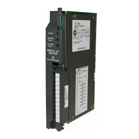
Chapter Introducing the Remote I/O Adapter Module Chapter Objectives This chapter describes the cat. no. 1771-ASB, series D remote I/O adapter module: module description and features hardware components Module Description and The remote I/O adapter module serves as an interface between remote I/O Features modules and programmable controllers. -
Page 11: Hardware Components
I/O RACK FAULT (red) A complete description of these indicators and how to use them for troubleshooting is explained in chapter 4. Figure 1.1 Remote I/O Adapter Module Switch S2 Switch S1 Diagnostic Indicators Field Wiring Configuration Jumpers 10796 I Allen-Bradley PLCs... -
Page 12: Summary
Chapter 1 Introducing the Remote I/O Adapter Module Module Switch Assemblies You must set two switch assemblies to configure your adapter module. Figure 1.2 shows the location of the switches. Figure 1.2 Switch Locations Switch Assembly Switch Assembly (S1) (S2) The S1 Assembly is used to select: the first I/O group number the I/O rack number... -
Page 13: Installing Your Module
54 and 56 lower connector: between 16 and 18 Figure 2.1 Keying Diagram Upper Connector Insert keying bands between: upper connector 54 and 56 lower connector 16 and 18 Keying Bands Allen-Bradley PLCs Lower Connector 12252... -
Page 14: Setting The Module Configuration Plugs
Chapter 2 Installing Your Module Setting the Module You need to set configuration plugs on the remote I/O adapter module to Configuration Plugs use 32-point I/O modules, . You access the plugs through the access hole on the left side of the module (Figure 2.2). Each plug is inserted on two pins of a three-pin connector. -
Page 15: Setting The Module Switches
– I/O scanner communication with or without complementary I/O (for PLC-2 family processors) scan - select whether the processor will scan all slots in the chassis, or all but the last four slots in the chassis Allen-Bradley PLCs... - Page 16 Chapter 2 Installing Your Module link response - unrestricted or series B emulation. Certain scanner modules with multiple communication ports require a delay in the link turnaround time to allow the central processing unit (CPU) in the scanner sufficient time to service all communication ports.
- Page 17 ON Primary chassis 10798 I OFF Complementary chassis Table 2.C I/O Rack Number and First I/O Group Switch Selections for the Address Switch Assembly S1 (PLC 2 Family Processors) Switch Selections I/O Rack Switch Selections First I/O Group Number Number Allen-Bradley PLCs...
- Page 18 Chapter 2 Installing Your Module Figure 2.5 Module Switch Assembly Settings for PLC 3 Family Processors Address Switch Assembly (S1) Switch Assembly (S2) Pressed in at top Closed (ON) Pressed in at bottom First I/O group number Open (OFF) (Table 2.D) I/O rack number (Table 2.D) Maximum I/O...
- Page 19 PLC 5/25 and PLC 5/30 processors can scan racks 01 07. PLC 5/40 and PLC 5/40L processors can scan racks 01 17. PLC 5/60 and PLC 5/60L processors can scan racks 01 27. PLC 5/250 processors can scan racks 0 37. Allen-Bradley PLCs...
- Page 20 Chapter 2 Installing Your Module Figure 2.7 Module Switch Assembly Settings for PLC 5 Family Processors With Complementary I/O Address Switch Assembly (S1) Switch Assembly Pressed in at top (S2) Closed (ON) Pressed in at bottom First I/O group number Open (OFF) (Table 2.F) I/O rack number...
-
Page 21: Setting The I/O Chassis Switches
If you have both primary and complementary in their last state when a fault occurs and machine chassis, set the primary chassis to ON and the motion may continue after fault detection. complementary chassis to OFF. 10802 I Allen-Bradley PLCs... - Page 22 Chapter 2 Installing Your Module Figure 2.9 I/O Chassis Backplane Switch Assembly Settings for Remote Adapter Module in PLC 3 Family Processor System ATTENTION: Set switch 1 to the OFF position to deenergize outputs wired to this chassis when Last State Switch a fault is detected.
- Page 23 When ON, processor can restart I/O chassis Always OFF When OFF, I/O chassis must be restarted at the chassis. Addressing Switches You select 1/2 slot addressing Always OFF You select 1 slot addressing You select 2 slot addressing Not allowed 10802 I Allen-Bradley PLCs 2-11...
-
Page 24: Setting The I/O Chassis Power Supply Configuration Plug
Chapter 2 Installing Your Module Setting the I/O Chassis You use the I/O chassis power-supply configuration plug (Figure 2.13) to Power Supply identify the type of power supply you use with your remote chassis. This Configuration Plug configuration plug is located on the backplane of series B I/O chassis. Figure 2.13 Series B I/O Chassis Power Supply Configuration Plug Settings For Use With:... - Page 25 I/O adapter module wiring arm. If this is unsuitable for your application, make your connections to terminals 1, 2, and 3 only. Allen-Bradley PLCs 2-13...
-
Page 26: Installing The Terminator
Chapter 2 Installing Your Module Installing the Terminator If this is the last remote I/O adapter on the link, you must use a terminating resistor to terminate both ends of the remote I/O link (scanner end and last adapter end). The size of the terminator is determined by the system configuration. -
Page 27: Module Installation
Note: The chassis locking bar will not close if all modules are not properly seated. Swing field wiring arm up into place and press firmly until it latches. Reapply system power and check for proper operation. Allen-Bradley PLCs 2-15... - Page 28 Chapter 2 Installing Your Module Summary In this chapter you learned how to install your adapter module. Chapter 3 tells you how to configure your module. 2-16...
-
Page 29: Addressing Modes For Your Remote I/O
I/O groups are made up of I/O terminals (Figure 3.1). An I/O group is an addressing unit that can contain up to 16 input terminals and 16 output terminals. You select an I/O chassis to have either 2-slot, 1-slot or 1/2-slot I/O groups. Allen-Bradley PLCs... - Page 30 Chapter 3 Addressing Modes for Your Remote I/O Figure 3.1 An I/O Group Up to 16 Input Terminals and 16 Output Terminals O u tp u t o r In p u t O u tp u t In p u t T e rm in a ls T e r m in a ls T e rm in a ls...
-
Page 31: Slot Addressing
1 block transfer and 1 8 point output module 2 block transfer modules B or later only 1 16 point input and output module 1 16 point and 1 8 point output module 1 8 point input and 1 16 point output module Allen-Bradley PLCs... - Page 32 Chapter 3 Addressing Modes for Your Remote I/O Using Standard density I/O (8 point) Modules Standard-density I/O modules provide eight input terminals or eight output terminals. Figure 3.3 illustrates the 2-slot I/O group concept with two 8-point input modules. Figure 3.4 shows an 8-point input module and an 8-point output module in a 2-slot I/O group.
- Page 33 16-point I/O modules use a full word in the input or output image table when they are addressed as a 2-slot I/O group (Figure 3.5). Two 16-point modules (one input and one output) can be used in a 2-slot I/O group. Allen-Bradley PLCs...
- Page 34 Chapter 3 Addressing Modes for Your Remote I/O Figure 3.5 16 point Input and Output Modules Using Two Words of the Image Table 2 slot I/O Group Input O utput T erm inals T erm inals O utput im age table w ord correspon ding to the I/O group.
- Page 35 Input im age table w ord corresponding to the I/O group. 10 07 06 05 17 16 15 14 03 02 01 00 Type of I/O module Module Terminal 1 = Input Number 0 = Output I/O Rack Number I/O Group Left Right Number Slot Slot 10808 I Allen-Bradley PLCs...
- Page 36 Chapter 3 Addressing Modes for Your Remote I/O Figure 3.7 Identifying 2 slot I/O Groups with Series B I/O Chassis 00 07 00 07 10 17 10 17 Example: Using I/O Group 0 and 16 point modules, a sample physical address (with its corresponding data table address) is: 2-slot I/O G roup Physical Address Module...
-
Page 37: Slot Addressing
O = O u tput M od ule 1 O utput m odule s use the sam e o utput im age table bits Allen-Bradley PLCs B T = B lock transfer M odule 2 C an be 8-point inp ut or ou tput m od ule o r single-slot block transfer m odule... - Page 38 Chapter 3 Addressing Modes for Your Remote I/O Follow these guidelines when configuring your remote system with complementary I/O chassis: Assign the complementary I/O rack number to a chassis of equal or smaller size than the primary chassis. If the complementary chassis is smaller than the primary one, set the last chassis switch on the complementary chassis to the ON position, unless the adapter is in the faulted I/O search mode.
- Page 39 When using double-slot block-transfer modules: The left slot of the complementary I/O group must be empty. Allen-Bradley PLCs You can only place an 8-point output module (if any) in the right slot of the complementary I/O group. 3-11...
- Page 40 Chapter 3 Addressing Modes for Your Remote I/O When using single-slot block-transfer modules: The right slot of the primary I/O group can be another single-slot block-transfer module, or an 8-point input or output module. The left slot of the complementary I/O group must be empty. You can place an 8-point output module in the right slot of the complementary I/O group;...
- Page 41 I / O I / O I / O I / O I / O I / O I / O 9 1 0 1 1 1 2 1 3 1 4 1 5 I/O Chassis Slot Number 14973 Allen-Bradley PLCs 3-13...
- Page 42 Chapter 3 Addressing Modes for Your Remote I/O Thirty-two-point I/O modules need 32 input or 32 output bits in the processor’s image table. Because only 16 input and 16 output bits are available for each I/O group, to address a 32-point I/O module, the remote I/O adapter module uses the unused input or output word associated with the adjacent I/O slot.
- Page 43 Standard density discrete I/O module in the left slot has terminals numbered 00 07. (Mark top only.) High density (16 point) discrete I/O module in either slot 10810 I has terminals numbered 00 07 and 10 17. Allen-Bradley PLCs 3-15...
- Page 44 Chapter 3 Addressing Modes for Your Remote I/O Module Placement with 1 slot Addressing Figure 3.14 shows possible module placement for complementary I/O with 1-slot addressing. Figure 3.14 Complementary I/O Configurations with 1 slot Addressing P r im a ry 1 6 -s lo t D ouble-slot C h a s s is I/O G ro u p...
-
Page 45: Assigning I/O Rack Numbers With 1 Slot Addressing
I/O rack number 1 to the remaining I/O group of the chassis. 1771 A4B I/O Chassis using 1 slot addressing 13077 Allen-Bradley PLCs You assign one I/O rack number to eight I/O groups, regardless of which addressing method you select. 3-17... -
Page 46: Slot Addressing 3
Chapter 3 Addressing Modes for Your Remote I/O When you select 1-slot addressing, each individual slot (one I/O group) is assigned to the corresponding word in the input or output image tables. You assign one I/O rack number to eight I/O groups (Figure 3.16). Figure 3.16 I/O Image Table and Corresponding Hardware for One Assigned Rack Number with 1 slot Addressing... -
Page 47: 1/2 Slot Addressing
Im a g e T a b le W o rd s A llo c a te d O u tp u t W o rd 1 fo r I/O G ro u p 1 U n u s e d 14259 Allen-Bradley PLCs 3-19... - Page 48 Chapter 3 Addressing Modes for Your Remote I/O Assigning I/O Rack Numbers with 1/2 slot Addressing The following rules apply when you assign I/O rack numbers for 1/2-slot addressing: One assigned I/O rack number is made up of eight I/O groups (Figure 3.18).
- Page 49 Number with 1/2 slot Addressing Output Im age Table W ord # Used I/O Group Designation An I/O chassis with 1/2 slot addressing I I O O Input/Output Designation Input Im age Table W ord # Always 14974 Allen-Bradley PLCs 3-21...
-
Page 50: Complementary I/O With 1/2 Slot Addressing
Chapter 3 Addressing Modes for Your Remote I/O Complementary I/O with Some processors support a complementary I/O configuration. Refer to the 1/2 Slot Addressing user’s manual for your processor to see if it supports this type of configuration. You configure complementary I/O by duplicating an I/O rack number of one I/O chassis (primary) in another I/O chassis (complementary), I/O group for I/O group. -
Page 51: Mixing 1 And 2 Slot Addressing In Individual Chassis
(Figure 3.20). Figure 3.20 Mixing Addressing Methods in Chassis Assigned One I/O Rack Number One Assigned I/O Rack Number 1771 A2B I/O Chassis 1771 A1B I/O Chassis using 2 slot addressing using 1 slot addressing Allen-Bradley PLCs 13126 3-23... -
Page 52: Acceptable Chassis Combinations
Chapter 3 Addressing Modes for Your Remote I/O Acceptable Chassis Not all chassis combinations are acceptable in making I/O rack number Combinations assignments. For example, a 1771-A4B I/O chassis cannot complete an assigned I/O rack number that starts in a 1771-A1 I/O chassis. Refer to Table 3.B for acceptable beginning I/O group numbers when making your I/O rack number assignments. -
Page 53: I/O Chassis/Adapter Module Combinations
1 slot and 1/2 slot addressing with 16 point and 32 point I/O modules. Summary In this chapter we discussed how to address your hardware and the various remote I/O configurations and options you can use in your remote system. Allen-Bradley PLCs 3-25... -
Page 54: Troubleshooting
Chapter Troubleshooting Chapter Objectives In this chapter, you will learn how to use the indicators on the module frontplate for troubleshooting the module. Troubleshooting With the The module has three indicators on the front plate, as shown in Figure 4.1. Indicator Lights Use these indicators for troubleshooting the module. - Page 55 I/O backplane or I/O module module Blink Communication on link. Chassis Possible shorted backplane in chassis. Check chassis, Replace chassis as violation. Excessive noise on backplane. necessary. Allen-Bradley PLCs...
-
Page 56: Summary
Chapter 4 Troubleshooting Indicators Active Adapter I/O Description Probable Cause Recommended Action Fault Rack Blink Module identification line fault Excessive noise on backplane Verify power supply and chassis grounding Module not communicating Power supply fault Check power supply, cable connections, and make sure adapter module is fully seated in chassis. -
Page 57: Specifications
Operational Temperature to 60 C (32 to 140 Storage Temperature to 85 C (-40 to 185 5% to 95% (without condensation) Relative Humidity Field Wiring Arm Cat. No. 1771-WB Field Wiring Arm Screw Torque 7 9 inch pounds Allen-Bradley PLCs... -
Page 58: Settings For 1771-As And 1771-Asb
Appendix Settings for 1771-AS and 1771-ASB Series A, B and C Remote I/O Adapters General Information This appendix provides information on previous remote I/O adapters supplied by Allen–Bradley. The following table lists the adapter and respective figure reference. Figure Description Applies to: Keying Diagram for 1771-ASB series A, B and C 1771-ASB series A, B and C... - Page 59 - 54 and 56 lower connector - 16 and 18 12252 Figure B.2 Keying Diagram for 1771-AS Remote I/O Adapter Insert keying bands between: upper connector - 44 and 46 lower connector - 20 and 22 12252 Allen-Bradley PLCs...
- Page 60 1 Line 1 Shield 2 Shield Cable Clear 3 Line 2 Allen-Bradley Cable (cat. no. 1770-CD) 4 No connection 5 No connection 6 No connection 7 No connection WARNING: Do not make connections to terminals 4 through 10. These terminals are connected internally (1 to 4, 8 No connection 2 to 5 and 3 to 6) and cannot be used for any other purpose.
- Page 61 OFF - Complementary chassis SD2 - with complementary I/O - ON - Primary chassis Always ON OFF - Complementary chassis 10819-I Table B.A I/O Rack Selection for PLC-2 Family Processors I/O Rack Switch Selections First I/O Group Switch Selections Number Number Allen-Bradley PLCs...
- Page 62 Appendix B Settings for 1771-AS and 1771-ASB Series A, B and C Remote I/O Adapters Figure B.5 Module Switch Assembly Settings for 1771-ASB series C Adapter for PLC 2 Family Processors Switch Assembly Address Switch Assembly (S2) (S1) Pressed in at top Closed (ON) Pressed in at bottom Open (OFF)
- Page 63 ON - 10,000 cable ft. max. (57.6K baud) 10820-I OFF - 5,000 cable ft. max. (115.2K baud) Table B.C I/O Rack Selection for PLC-3 Family Processors 1st I/O Switch I/O Rack I/O Rack Switch Setting Switch Setting Group Selections Number Number Number Allen-Bradley PLCs...
- Page 64 Appendix B Settings for 1771-AS and 1771-ASB Series A, B and C Remote I/O Adapters Figure B.7 Module Switch Assembly Settings for 1771-ASB series C Adapters for PLC 3 Family Processors Address Switch Assembly (S1) Switch Assembly (S2) Pressed in at top Closed (ON) Pressed in at bottom First I/O group number...
- Page 65 ON - 10,000 cable ft. max. (57.6K baud) 10821-I OFF - 5,000 cable ft. max. (115.2K baud) Table B.E I/O Rack Selection for PLC-5 Family without Complementary I/O Switch Selections I/O Rack Switch Selections First I/O Group Number Number Valid for PLC-5/25 processors only Allen-Bradley PLCs...
- Page 66 Appendix B Settings for 1771-AS and 1771-ASB Series A, B and C Remote I/O Adapters Figure B.9 Module Switch Assembly Settings for 1771-ASB series C Adapters for PLC 5 Family Processors Without Complementary I/O Address Switch Assembly (S1) Switch Assembly (S2) Pressed in at top Closed (ON)
- Page 67 OFF - 5,000 cable ft. max. (115.2K baud) Always ON Table B.G I/O Rack Selection for PLC-5 Family with Complementary I/O Switch Selections I/O Rack Switch Selections First I/O Group Number Number Valid for PLC-5/25 processors only Allen-Bradley PLCs B-10...
- Page 68 Appendix B Settings for 1771-AS and 1771-ASB Series A, B and C Remote I/O Adapters Figure B.11 Module Switch Assembly Settings for 1771-ASB series C Adapters for PLC 5 Family Processors With Complementary I/O Address Switch Assembly (S1) Switch Assembly Pressed in at top (S2) Closed (ON)
- Page 69 I/O group 0 with 2-slot Processor Restart Lockout - addressing and the PLC-3 is configured When ON, processor can restart I/O chassis in backup mode. When OFF, I/O chassis must be restarted at OFF - All other times. the chassis. 10824-I Allen-Bradley PLCs B-12...
- Page 70 Index addressing features of module, 1-slot, 3 13 field wiring arm, with 32-point modules, 3 14 connections, 2 12 1/2-slot, 3 19 2-slot, complementary I/O, using 16-point modules, I/O groups with 8-point modules, identifying, I/O groups, identifying with 1-slot addressing, 3 15 mixing 1 and 2-slot, 3 23...
- Page 71 PLC-3 with -AS, Series A or B adapter, troubleshooting guide, PLC-3 with Series C adapter, troubleshooting indicators, PLC-5 with -AS or -ASB Series A, B, with complementary I/O, B 10 PLC-5 with complementary I/O, B 11 PLC-5 with Series C, without vampire mode, complementary I/O, Allen-Bradley PLCs...
Need help?
Do you have a question about the 1771-ASB and is the answer not in the manual?
Questions and answers