Allen-Bradley D Series Installation Instructions Manual
Point i/o input modules
Hide thumbs
Also See for D Series:
- User manual (72 pages) ,
- Installation instructions manual (20 pages) ,
- Service manual (148 pages)
Table of Contents
Advertisement
Quick Links
Installation Instructions
Original Instructions
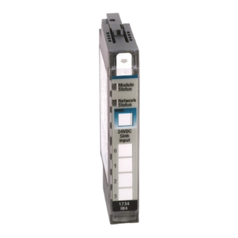
POINT I/O Input Modules
Catalog Numbers 1734-IB2, 1734-IB4, 1734-IB4K, 1734-IB8, 1734-IB8K, Series D
Topic
Summary of Changes
This publication contains the following new or updated information. This list includes substantive updates only and is not intended to reflect all changes.
Topic
Updated UK and European Hazardous Location Approval
Updated IEC Hazardous Location Approval
Updated Special Conditions for Safe Use
Updated General Specifications
Updated Environmental Specifications
Updated Certifications
Page
1
4
5
6
7
8
8
12
12
13
Page
3
4
4
14
14, 15
15
Advertisement
Table of Contents

Related Manuals for Allen-Bradley D Series


Summary of Contents for Allen-Bradley D Series
-
Page 1: Table Of Contents
Installation Instructions Original Instructions POINT I/O Input Modules Catalog Numbers 1734-IB2, 1734-IB4, 1734-IB4K, 1734-IB8, 1734-IB8K, Series D Topic Page Summary of Changes Before You Begin Install the Mounting Base Install the Module Install the Removable Terminal Block Remove a Mounting Base Wire the Module Communicate with the Module Interpret Status Indicators... - Page 2 POINT I/O Input Modules Installation Instructions ATTENTION: Read this document and the documents listed in the Additional Resources section about installation, configuration and operation of this equipment before you install, configure, operate or maintain this product. Users are required to familiarize themselves with installation and wiring instructions in addition to requirements of all applicable codes, laws, and standards. Activities including installation, adjustments, putting into service, use, assembly, disassembly, and maintenance are required to be carried out by suitably trained personnel in accordance with applicable code of practice.
- Page 3 POINT I/O Input Modules Installation Instructions Environment and Enclosure ATTENTION: This equipment is intended for use in a Pollution Degree 2 industrial environment, in overvoltage Category II applications (as defined in EN/ IEC 60664-1), at altitudes up to 2000 m (6562 ft) without derating. This equipment is not intended for use in residential environments and may not provide adequate protection to radio communication services in such environments.
-
Page 4: Before You Begin
POINT I/O Input Modules Installation Instructions IEC Hazardous Location Approval The following applies to products with IECEx certification: • Are intended for use in areas in which explosive atmospheres caused by gases, vapors, mists, or air are unlikely to occur, or are likely to occur only infrequently and for short periods. -
Page 5: Install The Mounting Base
Install the Mounting Base To install the mounting base on the DIN rail (Allen-Bradley® part number 199-DR1; 46277-3; EN50022), proceed as follows: WARNING: When used in a Class I, Division 2, hazardous location, this equipment must be mounted in a suitable enclosure with proper wiring method that complies with the governing electrical codes. -
Page 6: Install The Module
POINT I/O Input Modules Installation Instructions Position the mounting base vertically above the installed units (adapter, power supply, or existing module). Slide the mounting base down allowing the interlocking side pieces to engage the adjacent module or adapter. Press firmly to seat the mounting base on the DIN rail. The mounting base snaps into place. -
Page 7: Install The Removable Terminal Block
POINT I/O Input Modules Installation Instructions Insert the module straight down into the mounting base and press to secure. The module locks into place. Install the Removable Terminal Block A Removable Terminal Block (RTB) is supplied with your wiring base assembly. To remove, pull up on the RTB handle. This allows the mounting base to be removed and replaced as necessary without removing any of the wirings. -
Page 8: Remove A Mounting Base
POINT I/O Input Modules Installation Instructions WARNING: For 1734-RTBS and 1734-RTB3S, to latch and unlatch the wire, insert a bladed screwdriver (catalog number 1492-N90 – 3 mm diameter blade) into the opening at approximately 73° (blade surface is parallel with top surface of the opening) and push up gently. 73°... - Page 9 POINT I/O Input Modules Installation Instructions POINT I/O Module 1734-IB4, 1734-IB8, 1734-IB2 1734-IB4K 1734-IB8K 1734 1734 1734 NC = No connection C = Common Input 0 Input 1 Input 0 Input 1 Input 0 Input 1 V = Supply Input 2 Input 3 Input 2 Input 3...
- Page 10 POINT I/O Input Modules Installation Instructions Wiring for 1734-IB8, 1734-IB8K – Sink Input 3-wire 3-wire Prox Prox In 1 In 0 2-wire 2-wire Prox Prox In 2 In 3 3-wire 3-wire Prox Prox In 4 In 5 V = 12/24V DC 2-wire 2-wire C = Common...
- Page 11 POINT I/O Input Modules Installation Instructions Wiring Example for 1734-IB8, 1734-IB8K Using 3-Wire Proximity Switches Module Module Status Status DeviceNet Network Network Status Status System Power DeviceNet Power 1734 1734 OB8E Prox Prox Prox Prox Prox Prox Prox Prox 24V DC return 24V DC Terminal block with bus connector strip...
-
Page 12: Communicate With The Module
POINT I/O Input Modules Installation Instructions Communicate with the Module POINT I/O modules send (consume) and receive (produce) I/O data (messages). You map this data onto the processor memory. These modules produce 1 byte of input data (scanner Rx). It does not consume I/O data (scanner Tx). Default Data Map for 1734-IB2 Message size: 1 Byte Produces (Rx) -
Page 13: Specifications
POINT I/O Input Modules Installation Instructions Indicator Status for Modules Status Description No power applied to device. Green Device operating normally. Flashing green Device needs commissioning due to missing, incomplete, or incorrect configuration. Module status Flashing red Recoverable fault. Unrecoverable fault – may require device replacement. Flashing red/green Device is in self-test mode. - Page 14 POINT I/O Input Modules Installation Instructions General Specifications Attribute Value Terminal base screw torque 0.8 N•m (7 lb•in) Module location 1734-TB or 1734-TBS wiring base assembly Indicators, network status 1 green/red, logic side Indicators, module status 1 green/red, logic side 1734-IB2 –...
- Page 15 POINT I/O Input Modules Installation Instructions Environmental Specifications (Continued) Attribute Value IEC 61000-4-2: ESD immunity 6 kV contact discharges 8 kV air discharges IEC 61000-4-3: Radiated RF immunity 10V/m with 1 kHz sine-wave 80% AM from 80…6000 MHz IEC 61000-4-4: EFT/B immunity ±4 kV @ 5 kHz on signal ports Surge transient immunity...
- Page 16 Rockwell Otomasyon Ticaret A.Ş. Kar Plaza İş Merkezi E Blok Kat:6 34752 İçerenköy, İstanbul, Tel: +90 (216) 5698400 EEE Yönetmeliğine Uygundur Allen-Bradley, expanding human possibility, FactoryTalk, Logix 5000, POINT I/O, POINTBus, Rockwell Automation, RSLogix 5000, Studio 5000 Logix Designer, and TechConnect are trademarks of Rockwell Automation, Inc.
Need help?
Do you have a question about the D Series and is the answer not in the manual?
Questions and answers