Advertisement
Analog I/O Conversion Module
(Cat 1492-CM1771-LA001)
I. Description
This Analog I/O Conversion Module provides for the conversion of (1) 1771, 16 Channel I/O module to be
converted to (1) 1756, 16 Channel I/O module and consists of the following:
(1) 1771 Module (16ch) to (1) 1756 Module (16ch)
(2) Conversion Module: 1492-CM1771-LA001
(1) Cable: 1492-CONACAB005A or 1492-CONACAB005B (Table 2)
(1) Conversion Mounting Assembly: 1492-MUA... (Table 1)
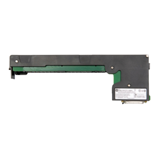
This conversion is accomplished without the removal of any field wires from the existing 1771 Swing Arm. The
existing 1771 Swing Arm fits directly onto the edge connector of the 1492 Conversion Module. On one end of the
1492 Cable is (1) connector for the Conversion Module. On the other end is the Removable Terminal Block (RTB)
for the 1756 I/O module, as shown in the photo below. The I/O signals are routed through the 1492 Conversion
Module and the 1492 Cable to the appropriate terminals on the 1756 I/O module per the Wiring Diagrams in
Section V. As standard, both portions of the 1492 Cables are 0.5M long, but we also offer a 1.0M cable length.
Refer to the footnotes in Table 2 for further details.
WARNING
PN-114287
DIR 10000060098 (Version 01)
Publication 1492-IN045B-EN-E
Printed in U.S.A.
Conversion Compatibility
and Product I.D. Label
25-Pin Connector for cable
1492-CONACAB005A OR -CONACAB005B
1492-CM1771-LA001 Conversion Module
De-energize and lockout any and all power to all I/O field devices connected to the A-B 1771 I/O chassis,
and the power to the 1771 I/O chassis itself. Ensure all power is de-energized and locked out to any
device in the control cabinet where the conversion is to be performed. Ensure work is performed by
qualified personnel.
Advertisement
Table of Contents

Related Manuals for Allen-Bradley 1771


Summary of Contents for Allen-Bradley 1771
- Page 1 This conversion is accomplished without the removal of any field wires from the existing 1771 Swing Arm. The existing 1771 Swing Arm fits directly onto the edge connector of the 1492 Conversion Module. On one end of the 1492 Cable is (1) connector for the Conversion Module. On the other end is the Removable Terminal Block (RTB) for the 1756 I/O module, as shown in the photo below.
- Page 2 3) Review the Max Slots for I/O and Chassis Width data from the Table 1 below. 4) Select a 1756 I/O Chassis which has enough I/O Slots. NOTE: (2) I/O slots are required in the 1756 Chassis for conversions where (1) 1771 I/O module converts to (2) 1756 I/O modules.
- Page 3 Foot Notes: To understand any issues concerning I/O module compatibility, refer to the Installation Manuals for the specific 1771 and 1756 I/O modules involved. The 3 numbers indicate the length of the 1492 Cable. Recommended cable lengths of 0.5M are shown.
- Page 4 See table 2 for other lengths. SHIELD GROUNDING: In some installations, the field wiring shield was grounded on the 1771 chassis. If this was the case, the installer must remove these shield connections from the 1771 chassis and they can be connected to the grounding stud on the 1492-CM1771-LA001 module.
- Page 5 See table 2 for other lengths. SHIELD GROUNDING: In some installations, the field wiring shield was grounded on the 1771 chassis. If this was the case, the installer must remove these shield connections from the 1771 chassis and they can be connected to the grounding stud on the 1492-CM1771-LA001 module.
- Page 6 See table 2 for other lengths. SHIELD GROUNDING: In some installations, the field wiring shield was grounded on the 1771 chassis. If this was the case, the installer must remove these shield connections from the 1771 chassis and they can be connected to the grounding stud on the 1492-CM1771-LA001 module.
- Page 7 See table 2 for other lengths. SHIELD GROUNDING: In some installations, the field wiring shield was grounded on the 1771 chassis. If this was the case, the installer must remove these shield connections from the 1771 chassis and they can be connected to the grounding stud on the 1492-CM1771-LA001 module.
- Page 8 PN-114287 DIR 10000060098 (Version 01) Publication 1492-IN045B-EN-E Printed in U.S.A.
Need help?
Do you have a question about the 1771 and is the answer not in the manual?
Questions and answers