
Related Manuals for Bruker minispec TC3


Summary of Contents for Bruker minispec TC3
- Page 1 minispec ● Temperature Unit TC3 User Manual Version 004 Innovation with Integrity...
- Page 2 © December 14, 2016 Bruker Corporation Document Number: 10000031931 P/N: H148851 For further technical assistance for this product, please do not hesitate to contact your nearest BRUKER dealer or contact us directly at: Bruker Corporation Am Silberstreifen 76287 Rheinstetten Germany Phone: + 49 721 5161 0 E-mail: minispec.SLS@bruker.com...
-
Page 3: Table Of Contents
Contents Contents About This Manual .......................... 5 Policy Statement ......................... 5 Symbols and Conventions .................... 5 Introduction............................ 7 Overview .......................... 7 Features.......................... 8 Intended Use........................ 8 Safety.............................. 9 Safety Notices........................ 9 3.1.1 Power Cord Set Requirements ................... 9 3.1.2 Power Cord Safety Maintenance .................. 9 3.1.3 Mains Disconnect........................ 9 3.1.4 Mechanical Hazards ...................... 10 3.1.5 Thermal Hazards ...................... 11 3.1.6... - Page 4 Contents Disposal Europe........................ 35 Disposal USA and Other Countries .................. 36 10 Contact .............................. 37 List of Figures........................... 39 List of Tables ............................ 41 Index .............................. 43 H148851_4_004...
-
Page 5: About This Manual
Options and accessories may or may not be illustrated in each figure. Policy Statement It is Bruker’s policy to improve products as new techniques and components become available. Bruker reserves the right to change specifications at any time. - Page 6 About This Manual WARNING WARNING indicates a hazardous situation, which, if not avoided, could result in death or serious injury. This is the consequence of not following the warning. 1. This is the safety condition. u This is the safety instruction. CAUTION CAUTION indicates a hazardous situation, which, if not avoided, may result in minor or moderate injury or severe material or property damage.
-
Page 7: Introduction
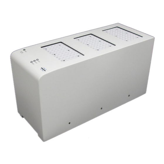
Introduction Introduction Overview The TC3 temperature unit, also called a dry bath, allows you to control the temperature of samples in an ASX-7000-series sample changer. It heats or chills the samples under the control of a host computer. Figure 2.1: The TC3 Unit. The temperature unit comes in three versions: •... -
Page 8: Features
Introduction Features Temperature Range Depending on the version, sample temperature can be maintained at 0° C to +110° C. Sample Changer Compatibility Use only with an ASX-7600 pick-and-place NMR sample changer. Chemical Compatibility Exposed surfaces are made of corrosion‑resistant stainless steel alloys or anodized aluminum. -
Page 9: Safety
Any obvious damage to the case (from a drop or fall) should be checked by service personnel for loose or damaged parts. Refer to the individual part lists, or contact Bruker, for approved replacement parts. 3.1.3 Mains Disconnect The power switch on the rear panel is not the mains disconnect. -
Page 10: Mechanical Hazards
Safety WARNING Fire and Shock Hazard Incorrect installation or use of the power supply may result in a fire or shock hazard. u Use only the provided power supply. u The power supply must be plugged into an outlet which has a protective ground connection. -
Page 11: Thermal Hazards
Safety 3.1.5 Thermal Hazards WARNING Burn Hazard Incorrect handling of vials or inserting fingers into any holes in the device may result in burn injuries. u Do not handle vials from heated zones until they have been given time to cool. u Do not attempt to insert fingers into any holes in the device. -
Page 12: Explanation Of Warning Labels
Safety WARNING Chemical Hazards Incorrect use of chemicals used in and near the device may result in injury or property damage. u Learn about the chemicals which will be used in and near the device, and observe the necessary precautions. u Always use appropriate personal protective equipment, including protective eyewear. -
Page 13: Electromagnetic Interference
Safety Electromagnetic Interference FEDERAL COMMUNICATIONS COMMISSION (FCC) NOTICE This equipment has been tested and found to comply with the limits for a Class A digital device, pursuant to Part 15 of the FCC Rules. These limits are designed to provide reasonable protection against harmful interference in a commercial installation. - Page 14 Safety H148851_4_004...
-
Page 15: Technical Data
Technical Data Technical Data Environmental Characteristics These environmental characteristics indicate the conditions for safe operation. Instrument performance may depend on the ambient conditions. Operating Temperature +5° C to +40° C (+41° F to +104° F) Non-Operating +0° C to +55° C (+32° to +131° F) Temperature Operating Altitude Up to 2,000 m (6,562 ft.) -
Page 16: Gas Connection
Technical Data Gas Connection One fitting is provided for nitrogen purge gas. The nitrogen source must be regulated to a pressure of no more than 35 kPa (5 psi, 0.35 bar). A typical gas flow of 0.5 liter/minute shall apply. Thermal Characteristics Temperature calibration and validation is performed at the factory. -
Page 17: Figure 4.2: Thermal Characteristics Of A 1-Zone 10 Mm Polymers Version
Technical Data Figure 4.2: Thermal Characteristics of a 1-Zone 10 mm Polymers Version Zone Default Range Ambient +5° C to +110° C H148851_4_004... -
Page 18: Figure 4.3: Thermal Characteristics Of A 2-Zone 26 Mm Version
Technical Data Figure 4.3: Thermal Characteristics of a 2-Zone 26 mm Version Zone Temperature Range Ambient +5° C to +80° C Ambient + 5° C to +80° C H148851_4_004... -
Page 19: Transport, Packaging And Storage
Transport, Packaging and Storage Transport, Packaging and Storage WARNING Lifting Hazard Lifting without assistance may cause injury. u Two people are required to lift the device. u Lifting should be done with a person situated on either side of the device. Inspect external packaging upon receipt for signs of shipping damage. - Page 20 Transport, Packaging and Storage H148851_4_004...
-
Page 21: Installation
Installation, initial commissioning, retrofitting, repairs, adjustments or dismantling of the device must only be carried out by Bruker Service or personnel authorized by Bruker. Damage due to servicing that is not authorized by Bruker is not covered by your warranty. H148851_4_004... - Page 22 Installation H148851_4_004...
-
Page 23: Operation
Operation Operation Power-On To turn the system on, first turn the temperature unit switch ON, then the sample changer. Power-Off To turn the system off, first turn the sample changer power switch OFF, then the temperature unit. In case of emergency, or before performing maintenance, remove the power cord from the back of the temperature unit and from the sample changer. - Page 24 Operation H148851_4_004...
-
Page 25: Maintenance
Maintenance Maintenance Replacing the Fuse WARNING Fire and Shock Hazard Using an incorrect fuse may cause fire or personal injury. . u Replace the fuses only with a 10A 250V slow-blow 5x20 mm fuse (T10AL250V). Two fuses are located in the power supply, just above the power cord connector. Figure 8.1: Fuse Holder for the TC3 •... -
Page 26: Replacing The Air Filter
• Plug the power cord back in. Replacing the Air Filter The 3-zone 10 mm SFC version of the TC3 includes a user-replaceable air filter. Contact Bruker for information on replacement filters. WARNING Laceration Hazard If the unit power is left on, the spinning fan blade just above the filter may cause injury. -
Page 27: Cleaning Instructions
Maintenance • Remove the old filter. If necessary, use your fingers to pull it out of the opening. Figure 8.4: Removing and Installing the Filter • Install the new filter. • Close the filter drawer. • Turn the power back on. Cleaning Instructions To clean the exterior surfaces of the device, complete the following steps: •... -
Page 28: Cleaning Broken Vials
• Flashlight. • Personal protective equipment. * A brush, micro cleaning attachment, and pestle are available from Bruker as an optional spare parts kit. If you supply your own, these items should be suitable for inserting into a 1.03 cm (0.407 in) diameter hole. -
Page 29: Cleaning Procedure
Maintenance Follow your workplace procedure for handling and disposing of broken glassware. Follow your workplace procedure for handling the sample material and for handling isopropyl alcohol. 8.4.1 Cleaning Procedure • Empty the shop vacuum. Doing so will help you keep shards of glass separate from other waste. -
Page 30: Figure 8.7: Bottle/Cylinder Brush
Maintenance Figure 8.7: Bottle/Cylinder Brush Figure 8.8: Inserting the Brush into the Broken Vial Figure 8.9: Removing the Broken Vial with the Brush H148851_4_004... -
Page 31: Figure 8.10: Steel Rod
Maintenance • Once the vial has been removed, use the steel rod or pestle to crush the remaining glass within the temperature controller. Repeatedly press down until the glass has been reduced to fine granules. Use the rod/pestle in the surrounding openings in the event any of the breakage spilled into them. -
Page 32: Figure 8.12: Shop Vacuum Attachment
Maintenance Figure 8.12: Shop Vacuum Attachment Figure 8.13: Using the Shop Vacuum Attachment to Remove Glass Particles • Once all the broken glass has been extracted, jet some isopropyl alcohol into the temperature controller. Use warm water and a mild detergent on the brush to clean any fat from the bottom of the heater/chiller block. -
Page 33: Figure 8.15: Using Warm Water And Detergent On The Brush To Clean The Bottom
Maintenance Figure 8.15: Using Warm Water and Detergent on the Brush to Clean the Bottom • Use a flashlight to check that all glass particles have been removed. • Use the brush to clean any overlooked debris. H148851_4_004... - Page 34 Maintenance H148851_4_004...
-
Page 35: Dismantling And Disposal
Installation, initial commissioning, retrofitting, repairs, adjustments or dismantling of the device must only be carried out by Bruker Service or personnel authorized by Bruker. Damage due to servicing that is not authorized by Bruker is not covered by your warranty. Dismantling Before starting dismantling: 1. -
Page 36: Disposal Usa And Other Countries
Only 100% pre-decontaminated equipment can and will be accepted by Bruker BioSpin. A release document for decontamination can be inquired from your nearest Bruker BioSpin contact site, also to be used when repairs, going back to Bruker sites, are requested. In compliance with WEEE II directive: 2012/19/EU Disposal USA and Other Countries Disposal of these materials may be regulated due to environmental considerations. -
Page 37: 10 Contact
WEEE DE43181702 Bruker BioSpin Hotlines Contact our Bruker BioSpin service centers. Bruker BioSpin provides dedicated hotlines and service centers, so that our specialists can respond as quickly as possible to all your service requests, applications questions, software or technical needs. - Page 38 Contact H148851_4_004...
-
Page 39: List Of Figures
List of Figures List of Figures Figure 2.1: The TC3 Unit........................ Figure 3.1: Bottom View with Filter Drawer Removed ..............Figure 3.2: Locaton of Warning Labels ................... Figure 4.1: Thermal Characteristics of a 3-Zone 10 mm SFC Version ........... Figure 4.2: Thermal Characteristics of a 1-Zone 10 mm Polymers Version ........ - Page 40 List of Figures H148851_4_004...
-
Page 41: List Of Tables
List of Tables List of Tables Table 4.1: Environmental Characteristics ................... Table 4.2: Electrical Characteristics....................H148851_4_004... - Page 42 List of Tables H148851_4_004...
-
Page 43: Index
Index Index Safety information .......... 9 Symbols and Conventions Safety ............ 5 Air filter ............. 26 Temperature avis Canadien........... 13 Operating............. 15 Temperature range........... 16 Tubing kinks ............ 19 cleaning ............ 27 condensation humidity ............ 19 Electrical characteristics ........ 15 FCC notice ............ 13 Filter.............. 26 Fuse .............. 25 humidity .......... 11, 15, 19 ICES 001 ............ 13 intended use ............ 8 interference ............ 13... - Page 44 Index H148851_4_004...
- Page 45 H148851_4_004...
- Page 46 ● Bruker Corporation info@bruker.com www.bruker.com Order No: H148851...
Need help?
Do you have a question about the minispec TC3 and is the answer not in the manual?
Questions and answers