Advertisement
Quick Links
Manual EN
ATICS-2-...-DIO, ATICS-4-...-DIO
ATICS-2-63A-DIO, ATICS-2-80A-DIO
ATICS-4-80A-DIO, ATICS-4-125A-DIO, ATICS-4-160A-DIO
Automatic transfer switching devices for safety power supplies
Software version: D333 V1.3x, D334 V1.3x, D335 V1.0
ATICS-2-DIO_D00080_05_M_XXEN / 04.2024
Advertisement

Related Manuals for Bender ATICS-4 DIO Series


Summarization of Contents
1 General information
1.1 How to use the manual
Instructions on manual usage and safety documentation.
1.2 Indication of important instructions and information
Explains danger, warning, caution, and advice symbols.
1.3 Signs and symbols
Displays common symbols for disposal, temperature, and recycling.
1.4 Service and Support
Provides contact information for customer service and repair.
1 General information
1.5 Training courses and seminars
Information on available training courses and seminars.
1.6 Delivery conditions
Details on the conditions of sale and delivery for products.
1.7 Inspection, transport and storage
Guidelines for inspecting, transporting, and storing devices.
1.8 Warranty and liability
Outlines exclusions for warranty and liability claims.
1 General information
1.9 Disposal of Bender devices
Instructions on proper disposal of Bender devices according to regulations.
2 Safety
Device-specific safety instructions
Safety precautions specific to ATICS® device functions and operation.
3 Intended use
Areas of application
Lists various locations and systems where ATICS® devices are used.
4 System description
4.1 Properties
Details the general characteristics and design of ATICS® devices.
4.2 Functional safety
Explains functional safety according to IEC 61508 and SIL2 suitability.
4.3 Application example
Illustrates a typical application scenario with system components.
4.4 ATICS® tasks
Lists the various tasks and functions performed by ATICS® devices.
4.5 ATICS® functions
Details the operational functions of ATICS® devices.
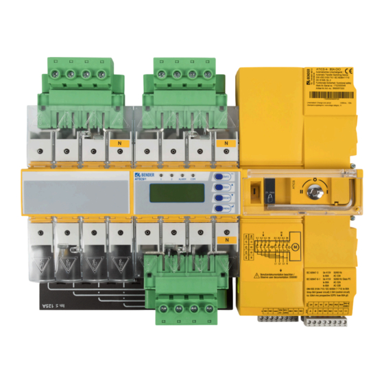
4.6 ATICS-2-DIO front view
Identifies and labels the front panel components of the ATICS-2-DIO model.
4.7 ATICS-4-DIO front view
Identifies and labels the front panel components of the ATICS-4-DIO model.
5 Mounting and connection
5.1 Mounting
Instructions on how and where to mount the ATICS® device.
Required tools
Lists the tools necessary for installation and connection.
5 Mounting and connection
5.1.3 Removing terminal cover
Steps for safely removing the terminal cover for access.
5.1.4 DIN rail mounting
Detailed instructions for mounting the device on a DIN rail.
5 Mounting and connection
5.1.5 Screw mounting on plate
Instructions for mounting the device using screws on a plate.
5.2 Connection
General guidelines for connecting the device.
5.2.1 Short-circuit protection
Guidance on selecting appropriate short-circuit protection devices.
5 Mounting and connection
5.2.2 Connecting ATICS® safely
Critical safety procedures for connecting the device.
Connection Safety Warnings
Critical safety warnings for connection, testing, and phase failure.
5.3 Other functions
5.3.1 Sealing the transparent cover
Instructions on how to seal the transparent cover for security.
5.3.2 Manual mode
Details on entering and using manual mode, including safety advice.
5.3 Other functions
5.3.3 Lock ATICS® with a padlock
Steps for locking the device in manual mode using a padlock.
6 Commissioning, settings and testing
6.1 Design and installation
Considerations for the proper installation and design of the system.
6.1.1 Safety advice
Crucial safety advice for commissioning and setup.
6.1.2 Setting parameters of indicator devices
How to configure connected alarm indicators and operator panels.
6.1 Design and installation
6.1.3 ATICS® messages on the BMS bus (channel use)
Explains how ATICS® messages are transmitted via the BMS bus.
6.1 Design and installation
6.1.3 ATICS® messages on the BMS bus (channel use) (ATICS-4-DIO)
Explains BMS bus message transmission specific to ATICS-4-DIO.
6.1.4 Tests, decommissioning
Procedures for testing and safely decommissioning the device.
6.2 Setting and testing according to the checklist
How to perform settings and tests using a checklist.
7 Operation
7.1 Operating and display elements
Identifies and describes the function of LEDs, buttons, and the display.
7 Operation
7.2 Quick reference guide
Provides quick access to common operational information.
7.2.1 Display under normal operating conditions
Explains how to interpret the display during normal operation.
7.2.2 Display during fault condition
Describes how to interpret the display during fault conditions.
7 Operation
7.2.3 Test function
Details how to perform various functional tests on the device.
7 Operation
7.2.3 Test function (continued)
Further explanation and conditions for performing tests.
7 Operation
7.2.3.1 Test menu 1: Autom. changeover
Steps for performing an automatic changeover test.
7.2.3.2 Test menu 2: Manual changeover
Steps for performing a manual changeover test.
7 Operation
7.2.3.3 Test menu 3: Last changeover
How to save the last changeover operation as a test.
7 Operation
7.2.3.4 Test menu 4: Generator
Instructions for testing the generator connection and function.
7 Operation
7.2.3.5 Test menu 5: Test communication
Procedure for testing BMS bus communication by simulating alarms.
7.2.4 Reset function
How to reset alarms, fault messages, and switch-back locks.
7.2.4 Reset function
7.2.4.1 Reset menu 1: Alarm
Steps to reset alarm and fault messages on the device.
7.2.4.2 Reset menu 2: SwitchBackLock
How to disable the switch-back lock function.
7.2.4 Reset function
7.2.4.3 Reset menu 3: Changeover
How to reset or adjust changeover limit values.
7.2.4 Reset function
7.2.4.4 Reset menu 4: Service alarm
How to reset service prewarnings and set the next service date.
8 Menu mode: Operation and setting
8.1 Switching on and calling up the main menu
Initial steps to power on and access the main menu.
8 Menu mode: Operation and setting
8.2 Menu overview diagram
A visual map of the device's menu structure.
8.3 Function of the main menu
8.3.1 Menu 1: Alarm/meas.values
Displays saved status, alarms, and measured values.
8.3 Function of the main menu
8.3.2 Menu 2: Changeover
Displays information about changeover function, numbers, and tests.
8.3.3 Menu 3: History/Loggers
Accesses logs for alarms, values, settings, tests, and service.
8.3.4 Menu 4: Settings
8.3.4.1 Settings menu 1: Changeover
Configuration options for changeover timing and parameters.
8.3.4 Menu 4: Settings
8.3.4.2 Settings menu 2: Voltage
Settings for voltage monitoring on input lines.
8.3.4 Menu 4: Settings
8.3.4.3 Settings menu 3: Current
Settings for current monitoring and short-circuit detection.
8.3.4 Menu 4: Settings
8.3.4.4 Settings menu 4: Relay
Configuration for the operation and function of the alarm relay output.
8.3.4 Menu 4: Settings
8.3.4.5 Settings menu 5: Dig. input
Settings for the mode and function of digital inputs.
8.3.4 Menu 4: Settings
8.3.4.6 Settings menu 6: Data loggers
Settings for configuring data loggers to record measured values.
8.3.4 Menu 4: Settings
8.3.4.7 Settings menu 7: Language
Option to select the display language for menus and messages.
8.3.4.8 Settings menu 8: Interface
Settings for BMS bus address, interface changes, and failure monitoring.
8.3.4 Menu 4: Settings
8.3.4.9 Settings menu 9: Clock
Setting the device's date and time for logging purposes.
8.3.4.10 Settings menu 10: Password
Managing passwords for settings and test menus.
8.3.4 Menu 4: Settings
8.3.4.11 Settings menu 11: Service
Access for authorised service personnel for diagnostics and settings.
9 Troubleshooting
9.1 Fault and alarm messages
Overview of fault and alarm messages provided by the ATICS® device.
9.1.1 Plain text messages
Lists plain text fault messages and their corresponding actions.
9.1 Fault and alarm messages
9.1.2 Messages with error code or service code
Lists messages with error codes and required actions.
9 Troubleshooting
9.2 Frequently asked questions
Answers common questions regarding device behavior and messages.
10 Periodic verification and service
10.1 Periodic verification
Guidelines and requirements for periodic verification of electrical installations.
10.2 Maintenance
Recommendations for regular maintenance checks.
10.3 Cleaning
Instructions on how to clean the device.
10 Periodic verification and service
10.4 Operation with bypass switch
How to operate the device using an optional bypass switch.
10.5 Replacing ATICS®
10.5.1 Removing existing ATICS®
Step-by-step guide to safely remove the ATICS® device.
10.5 Replacing ATICS®
10.5.2 Installing a new ATICS®
Instructions for installing a new ATICS® device.
11 Technical data
11.1 Technical data ATICS-...-DIO
Detailed technical specifications for ATICS-...-DIO devices.
11 Technical data
11.2 TÜV test report according to VDE 0100 Part 710
TÜV test report detailing electrical safety compliance.
11 Technical data
11.3 TÜV certificate regarding functional safety
Certificate confirming functional safety compliance (SIL2).
11 Technical data
11.4 Standards and certifications
List of standards and certifications the device complies with.
11.5 Ordering information
Information on ordering different ATICS® variants and accessories.
11.5 Ordering information
11.6 Additional documents
Lists other related documents available for ATICS® devices.
11.7 Document revision history
Records changes made to the document over different versions.
Need help?
Do you have a question about the ATICS-4 DIO Series and is the answer not in the manual?
Questions and answers