
Summary of Contents for Lovato T-FIRE MODUL
- Page 1 T-FIRE MODUL Modulo di separazione Separation unit Istruzioni per l’installazione, l’uso e la manutenzione Assembling instructions and maintenance...
-
Page 2: Sezione 6: Installazione
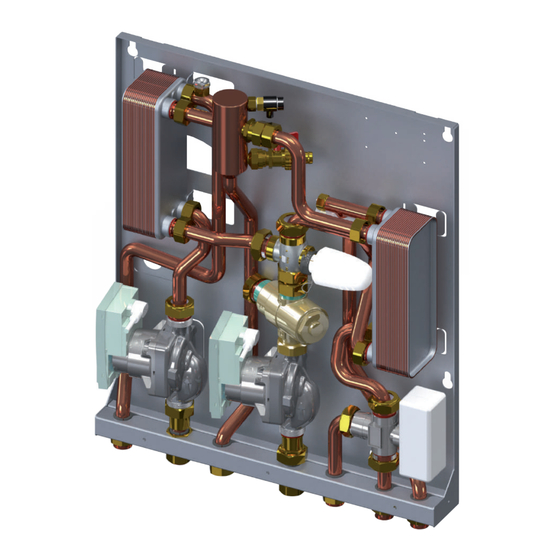
SEZIONE 8: REGOLATORE DIGITALE Illustrazioni e dati presenti si intendono non impegnativi. LOVATO Spa si riserva il diritto di apportare modifiche senza obbligo di preavviso. È vietata la riproduzione parziale o totale di disegni, testi o illustrazioni senza autorizzazione scritta. - Page 3 DESCRIZIONE Il modulo T-FIRE MODUL è un sistema di separazione adatto per l’abbinamento tra generatori a combustibile solido a vaso aperto e tradizionali con alimentazione a gas con molteplici funzionalità, tra le quali riscaldamento, anticondensa, produzione ACS e carico boiler sanitario.
- Page 4 Installazione, uso e manutenzione SEZIONE 2: DATI TECNICI T-FIRE MODUL STRUTTURA MODULO BASE: Circolatore di riscaldamento ad alta efficienza Wilo YONOS PARA RS 15/1-6 180 RKA FSM9 (alternativa circ. 3 velocità Wilo RS 15/6-3 Ku); Scambiatore di calore a piastre inox saldobrasate;...
- Page 5 Scambiatore di calore a piastre inox saldobrasate (primario); Sistema di degasazione / defangazione con rubinetto di scarico e valvola di sfiato aria manuale; Valvola anticondensa (fornito separatamente). Accessori SCHEMA DI IMPIANTO T-FIRE MODUL standard SCHEMA DI IMPIANTO T-FIRE MODUL standard T-FIRE MODUL T-FIRE MODUL Centralina di gestione...
- Page 6 Installazione, uso e manutenzione SEZIONE 3: ACCESSORI DI COMPLETAMENTO Valvola anticondensa La valvola anticondensa impedisce la formazione di condensa e fuliggine all’interno del generatore a combustibile solido. Mette in comunicazione la mandata ed il ritorno del circuito primario impeden- done un eccessivo Delta T. Infatti, all’accensione del termocamino, la valvola è...
- Page 7 Installazione, uso e manutenzione SEZIONE 4: DATI TECNICI KIT BOLLITORE (Accessorio) STRUTTURA KIT “B” CARICO BOLLITORE: Valvola deviatrice a 3 vie di priorità DN15; Servomotore reversibile 230 V + relay; Kit tubazioni di collegamento. PERDITA DI CARICO CIRCUITO PRIMARIO CON KIT BOLLITORE / CURVE CARATTERISTICHE CIRCOLATORI 68,6 Wilo RS 15/7-3 KU 58,8...
- Page 8 ¾” F ¾” F Installazione accessori (solo se ordinati in un secondo momento) T-FIRE MODUL con kit CARICO BOLLITORE “B” a - Intercettare il modulo T-FIRE attraverso gli appositi rubinetti di intercettazione (forniti separatamente) b - Svitare i tappi rif. 1 come da figura e rimuovere il tubo facendo attenzione alla fuoriuscita di eventuale acqua residua all’interno...
- Page 9 Installazione, uso e manutenzione SCHEMA IMPIANTO T-FIRE MODUL con kit CARICO BOLLITORE T-FIRE MODUL Centralina di gestione Utenza (circuito secondario) Caldaia a gas Caldaia a combustibile solido a vaso aperto Uscita ACS Rete AFS COLLEGAMENTO ELETTRICO T-FIRE MODUL con kit BOLLITORE “B”...
- Page 10 Installazione, uso e manutenzione SEZIONE 5: DATI TECNICI KIT SANITARIO (Accessorio) STRUTTURA KIT “S” ACS ISTANTANEA: Valvola deviatrice a 3 vie con concetto proporzionale, rego- lata termostaticamente con attuatore 20-50°C (descrizione funzionamento valvola - sezione “componenti”); Scambiatore di calore a piastre inox saldobrasate; Valvola deviatrice a 3 vie di priorità...
- Page 11 ¾” F ¾” F ¾” F ¾” F Installazione accessori (solo se ordinati in un secondo momento) T-FIRE MODUL con kit ACS “S” a - Intercettare il modulo T-FIRE attraverso gli appositi rubinetti di intercettazione (forniti separatamente) b - Svitare i tappi rif. 1 come da figura e rimuovere il tubo facendo attenzione alla fuoriuscita di eventuale acqua residua all’interno...
- Page 12 <2 bassa conduttività termica, una riduzione delle prestazioni lato sanitario. Idrogeno Carbonato mg/l <300 I materiali di costruzione del kit ACS del prodotto T-FIRE MODUL sono Idrogeno Carbonato/Solforato mg/l >1.0 conformi a quanto previsto dal D.M. 174/2004, regolamentato dalla Direttiva 98/83/CE.
- Page 13 Installazione, uso e manutenzione T-FIRE MODUL con kit ACS “S” SONDA MANDATA TERMOCAMINO LINEA VALV 230 Vac 230 Vac 230 Vac Cons. Cald 230 Vac 1 2 3 4 5 6 7 8 9 10 11 12...
-
Page 14: Controlli Preliminari
Installazione, uso e manutenzione SEZIONE 6: INSTALLAZIONE CONTROLLI PRELIMINARI Prima di ogni operazione rimuovere con cura l’imballo e controllare la perfetta integrità dell’apparecchiatura. Nel caso si evidenziassero dei difetti o dei danni non installare o cercare di riparare l’apparecchiatura ma rivolgersi al venditore. Smaltire le parti di imballaggio in accordo con leggi e disposizioni vigenti. Il prodotto viene fornito dalla casa produttrice a tenuta. - Page 15 Installazione, uso e manutenzione N.B. TASSELLI ESCLUSI DALLA IMPORTANTE! FORNITURA POSIZIONARE IL MODULO IN MANIERA CORRETTA 2a 2a Fissare a muro n.4 tasselli da 12 mm (fig.2), rispettando le distanze come da rif. 2a. Apllicare il modulo a muro nei tasselli utilizzando le ap- posite asole nella parte posteriore del modulo.
- Page 16 (fig. 5). N.B. T-FIRE MODUL viene fornito con apposito tubicino in PVC collegato alla valvola di sfiato aria manuale per agevolare le operazioni di sfiato aria, ed evitare danni a persone o compo-...
- Page 17 VALV 230 Vac 230 Vac Installazione, uso e manutenzione 230 Vac SONDA SEZIONE 8: REMOTIZZAZIONE REGOLATORE DIGITALE BOLLITORE SONDA MANDATA TERMOCAMINO TA CALDAIA COLLEGAMENTO A CURA DELL'INSTALLATORE VALV 230 Vac 230 Vac 230 Vac LINEA ALIMENTAZIONE 230 V VALV KIT PER REMOTIZZAZIONE REGOLATORE DIGITALE TC110C-65 Fig.7 SONDA MANDATA TERMOCAMINO...
- Page 18 Installazione, uso e manutenzione SEZIONE 8: REGOLATORE DIGITALE TC110 24C-65 Valv 1 2 3 4 5 6 7 8 9 10 11 12 Fig. 1 Aspetto esterno e Schema dei collegamenti elettrici i t t Sensore NTC10K@25° -50÷120°C Sonda Termocamino Misura: 0÷99°C ±...
- Page 19 Installazione, uso e manutenzione Funzionalità: Accensione/Spegnimento L’accensione/Spegnimento della centralina si effettua con la pressione prolungata del tasto K4 Lo stato SPENTO è segnalato dalla accensione del led OFF All’accensione della centralina viene visualizzata la seguente sequenza di messaggi Codice Prodotto Revisione prodotto r1.0 Configurazione Kit...
- Page 20 Installazione, uso e manutenzione Funzionamento USCITE: Configurazione 1: Modulo di scambio vaso aperto-impianto e gestione sanitario istantaneo POMPA1 ON: se temperatura sonda S1 superiore al termostato e temperatura sonda S1-S2 superiore al termostato o temperatura sonda S1 superiore al termostato sicurezza P01=1 se sicurezza abilitata POMPA2 ON:...
- Page 21 Installazione, uso e manutenzione Parametri Menu INSTALLATORE Cod. U.m. Fabbrica A 01 Termostato funzione ALLARME su sonda S1 °C A 02 Termostato di SICUREZZA su sonda S1 °C A 03 Termostato di ANTIGELO ‘ICE’ su sonda S1 °C Termostato differenziale S1-S2 °C A 31...
- Page 22 SECTION 7: REPLACEMENT OF THE ELECTRIC SERvOMOTOR AND INSTALLATION’S POSITION Picture and technical data are not binding. LOVATO Spa will reserve the right to bring change without obbligation of notice. It is forbidden reproduce copy, drawing or texties, partial or total without previous written authorization.
-
Page 23: Section 1: Introduction
LOVATO S.p.A. is not responsible for the product modified without permission, and for the replamcements of no-original components. Electrical connection The controller must be installed and connected by authorized staff according to applicable regulations. -
Page 24: Electrical Specifications
Assembling instrunctions and maintenance SECTION 2: T-FIRE MODUL TECHNICAL DATA COMPONENTS: High efficiency pump type Wilo YONOS PARA RS 15/1-6 180 RKA FSM9 (alternative pump type Wilo RS 15/6-3 Ku); Brazed plate iron steel heat exchanger; Degasser / dirty separator system;... -
Page 25: Hydraulic Scheme
Primary circulation pump (separately supply); Brazed plate iron steel heat exchanger (primary circuit); Degasser / dirty separator system with drain tap and manual air vent valve; Anticondensation kit (separately supply). Accessories ExAMPLE OF APPLICATION T-FIRE MODUL Controller User (secondary circuit) Boiler Boiler-Fireplace stove... -
Page 26: Section 3: Accessories
Assembling instrunctions and maintenance SECTION 3: ACCESSORIES Anticondensation valve The anticondensing valve prevent the formation of condensation and soot inside the soild fuel boiler. It connects the flow and return of the primary circuit preventing the excess Dt. When the fireplace starting up, the valve is completely open to the return line until the setting temperature is obtained. - Page 27 Assembling instrunctions and maintenance SECTION 4: DHW TANK KIT TECHNICAL DATA (accessory) COMPONENTS: DN15 3-port motorized diverting valve; Actuator 230 V with relay; Pipes. PRESSURE LOSS PRIMARY CIRCUIT WITH DHW TANK KIT/ PUMP CHARACTERISTICS 68,6 Wilo RS 15/7-3 KU 58,8 49,0 Wilo YONOS PARA 25/1-6 39,2...
- Page 28 ¾” F Accessories installation (Only for separately supply) T-FIRE MODUL with kit “B” DHW TANK a - Shut off the ball valves of the T-Fire (separately supplied) b - Unscrew the caps ref.1 as shown in the picture and remove the pipe c - Remove the tap ref.2...
-
Page 29: Electric Connection
Assembling instrunctions and maintenance ExAMPLE OF APPLICATION T-FIRE MODUL Controller User (heating circuit) Boiler Boiler - fireplace stove DHW outlet Rete AFS ELECTRIC CONNECTION STORAGE TANK PROBE FLOW SENSOR Fireplace stove LINE VALVE 230 Vac 230 Vac 230 Vac Cons. Cald... - Page 30 Assembling instrunctions and maintenance SECTION 5: DHW PRODUCTION KIT TECHNICAL DATA (Accessory) COMPONENTS: DN20 3-port diverting thermostatic proportional valve, con- trolled by thermostatic actuator from 20 to 50°C (see chapter “DHW production components description”); Brazed plate iron steel heat exchanger; DN15 3-port motorized diverting valve with actuator;...
-
Page 31: Dimensions And Connections
¾” F ¾” F Accessories installation (Only for separately supply) T-FIRE MODUL with kit “S” DHW PRODUCTION a - Shut off the ball valves of the T-Fire (separately supplied) b - Unscrew the caps ref.1 as shown in the picture and remove the pipe c - Remove the tap ref.2... - Page 32 Assembling instrunctions and maintenance ExAMPLE OF APPLICATION DHW outlet T-FIRE MODUL Controller User (heating circuit) Caldaia a gas Boiler - Fireplace stove DCW inlet LIMIT VALUES FOR COPPER SOL- DESCRIPTION UNIT DERED HEAT EXCHANGER 7-9 (including saturation factor) IMPORTANT Saturation factor(delta PH)) -0.2<0<+0.2...
-
Page 33: Electric Connections
Assembling instrunctions and maintenance ELECTRIC CONNECTIONS FLOW SENSOR Fireplace stove LINE VALVE 230 Vac 230 Vac 230 Vac Cons. Cald 230 Vac 1 2 3 4 5 6 7 8 9 10 11 12... -
Page 34: Section 6: Installation
Assembling instrunctions and maintenance SECTION 6: INSTALLATION PRELIMINARY CHECK Before every operation carefully remove the packaging and verify if there is external damages. In case of damages please do not install the products. Dispose the packaging parts in compliance with the local regulations. The product is supplied by the manufacturer completely screwed. - Page 35 Assembling instrunctions and maintenance SCREW ANCHORS NOT IMPORTANT! SUPPLIED PLACE THE BRACKET IN THE CORRECT PLACE 2a 2a Fix No. 4 plugs on the wall (pic. 2) respecting the distance as shown in rif.2a. Install the module on the the plugs through the slots on the back of the module.
-
Page 36: Section 7: Module Start Up
In the open circuits can be necessary to vent the air more time (pic.4) and flush the deposit of impurity by the valve (pic.5). N.B: T-FIRE MODUL is supplied with PVC pipe connected to the air vent valve in order to make easier the operation of venting, avoiding damages to the people or electric components of the... - Page 37 Assembling instrunctions and maintenance SECTION 8: REMOTE KIT DIGITAL CONTROLLER REMOTE KIT DIGITAL CONTROLLER TC110C-65 Fig.7 If you need to install a remote controller, nr. 2 terminal boards ( male+female) will be added into the package as shown in the pic.7 The connection will be made jointing the pre-wired male terminal bo- ard (pic.6) to the female terminal board as shown in the picture 8.
- Page 38 Assembling instrunctions and maintenance SECTION 8: DIGITAL CONTROLLER TC110 24C-65 Valv 1 2 3 4 5 6 7 8 9 10 11 12 Fig. 1 Aspetto esterno e Schema dei collegamenti elettrici Fig. 1 External aspect and electrical connection diagram i t t Sensore NTC10K@25°...
-
Page 39: Standby Function
Assembling instrunctions and maintenance ON/OFF The ON/OFF of the controller is through the prolonged pressure of the button K1 The OFF state is signalled with the blinking led OFF Visualizations Normally the display shows sensor 1 temperature. The sensor 2 temperature is showed by the prolonged pressure of K1 ALARM Function If the temperature read by the sensor is over the value Alarm Thermostat (A90°C) The acoustic and visual signal is activated... - Page 40 Assembling instrunctions and maintenance OUTPUT functioning Configuration 1: Open vented-heating system exchange module and instantaneous DHW PUMP 1 ON: S1 > A04 And S1-S2 > A31 S1 > A02 P01=1 (safety enabled) POMPA2 ON: S1 > A06 And S1-S2 > A31 S1 >...
-
Page 41: Fault Finding
Assembling instrunctions and maintenance MAIN Menu Through the click of the button K1 the current values of the thermostats are visualized signalled by the correspondent blinking led P1 / VALV / P2 To modify: Chose the value to modify Through the buttons K3 and K2 increase/decrease the value To memorize, wait for about 5 seconds or scroll the values with the button K1 MAIN Menu Parameters U.M. - Page 42 Smart Energy Solutions www.lovatospa.com LOVATO S.p.A. Via Selva, 4/a +39 045 618 2012 mail 37040 Gazzolo d’Arcole info@lovatospa.com lovatospa fax+39 045 618 2017 VERONA - ITALY...
Need help?
Do you have a question about the T-FIRE MODUL and is the answer not in the manual?
Questions and answers