Advertisement
Quick Links
ISO Registered Company
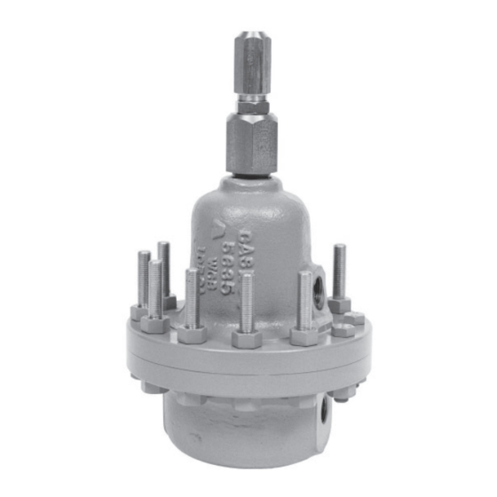
MODEL 123-1+6+S DIFFERENTIAL
I. DESCRIPTION AND SCOPE
The Model 123-1+6+S Differential is designed for high pressure liquid or gas applications to Cashco drawing nos.
32934 (NACE construction) and 32935 (Non-NACE construction). It is used to control differential upstream (inlet or
P
) pressure and a loading (P
1
25, and 40).
This is not a safety device and must not be sub sti tut ed for a code approved pres sure safety
relief valve or rupture disc. NOT FOR STEAM SERVICE. NOT FOR OXYGEN SERVICE.
II. INSTALLATION
This unit was designed and is used almost exclusively on compressor and turbo expander seal systems. REFER
TO COM PRES SOR/EXPANDER MANUFACTURER'S MANUAL FOR DE TAILED INSTALLATION, START-UP
AND SHUTDOWN OF THIS UNIT. Install regulator with Inlet (P
in accordance with the directional flow arrow cast on body (1).
IIl. PRINCIPLE OF OPERATION
1. Movement occurs as pressure variations reg is ter
on the diaphragm (3). The registering pressure is
the inlet (P
) or upstream pressure which reg is ters
1
on the "un der neath" side of the diaphragm (3). The
second pressure registered is the loading (P
pressure in the spring chamber (2) "above" the
diaphragm (3). The range spring (18) determines
the differential pres sure setpoint (P
∆ P
= P
- P
SIZING
1
2
P
> P
1
LOAD
P
= P
+ P
1
LOAD
SET
∆ P
= P
- P
DIFFERENTIAL
1
LOAD
INLET
@ P
1
OUTLET @ P
Model 123-1+6+S Differential Schematic
INSTALLATION, OPERATION & MAIN TE NANCE MANUAL (IOM)
BACK PRESSURE / RELIEF REGULATOR
) pressure to a rotating shaft seal. Sizes are 1/2", 3/4", 1", and 1-1/2" (DN15, 20,
Load
). As inlet
SET
RANGE SPRING:
SETTING @ P
SET
LOADING FLUID
@ P
LOAD
DIA PHRAGM
(Optional)
INLET
@ P
1
2
SECTION I
CAUTION
SECTION II
) pressure coming in the side body (1) connection
1
SECTION III
(P
) pressure drops, the range spring (18) pushes
1
the diaphragm (3) down, clos ing the port; as
inlet (P
pushes up and the port opens. As the loading
(P
LOAD
tends to follow. An increase in (P
inlet (P
)
a decrease in (P
LOAD
pres sure.
2. A complete diaphragm (3) failure will cause the
fluids to mix in the spring chamber (2) or loading
pressure piping. Reg u la tor action will "fail close"
under a di a phragm (3) failure.
3. Under normal operating conditions, the inlet (P
pressure should be greater than the loading
(P
LOAD
setpoint.
Limit any field hydrostatic test to 1-1/2 times the
Maximum Pressure Rat ing (See Ta ble 1). En sure
that the test pressure is applied uniformly to the
body inlet, body outlet, and spring chamber.
) pressure increases, the diaphragm (3)
1
) pressure varies, the inlet (P
) pressure by nearly an equal amount ;
1
) will decrease the inlet (P
LOAD
) pressure by the range spring (P
CAUTION
IOM-123 1+6+S
DIFF
02-16
) pressure
1
) will increase
LOAD
)
1
)
1
)
SET
Advertisement

Related Manuals for cashco 123-1+6+S


Summary of Contents for cashco 123-1+6+S
- Page 1 SECTION I I. DESCRIPTION AND SCOPE The Model 123-1+6+S Differential is designed for high pressure liquid or gas applications to Cashco drawing nos. 32934 (NACE construction) and 32935 (Non-NACE construction). It is used to control differential upstream (inlet or ) pressure and a loading (P ) pressure to a rotating shaft seal.
-
Page 2: Maintenance
TABLE 1 MAX OPERATING PRESSURES & TEMPERATURE RATING SPECIFICATIONS NPT and 1500# ANSI Flg. 600# ANSI Flg. 900# ANSI Flg. 100°F 400°F 100°F 400°F 100°F 400°F DESCRIPTION (38°C) (205°C) (38°C) (205°C) (38°C) (205°C) psig (Barg) psig (Barg) psig (Barg) psig (Barg) psig (Barg) - Page 3 New body flange hardware (7,8,30,41,42) may be con sist ing of the pis ton (14), piston nut (6), pur chased from Cashco, Inc. or through the OEM. di a phragm (3), di a phragm cov ers (24) (NACE unit only, Cashco Dwg. 32934), pres sure 7.
- Page 4 CCW. NOTE: For 1-1/2" (DN40) body reduced orifice only, also remove the a. NACE variation only (Cashco Dwg. cylinder bush ing (33) at this time. See Figure #32934): Place one of the two di a phragm cover(s) (24) over piston (14) post.
- Page 5 Adjust length of studs Recommended Bench Test Figure 2: (41,42) by using the top nut (8) to allow at Piping Schematic for 123-1+6+S least 3-4 threads protruding from the lower nut (8). dif fer en tial setting, check seat leak age Torque body flange hardware (7,8,30,41,42) at 40% below 15 psig (1.0 Barg);...
-
Page 6: Troubleshooting Guide
SECTION VII VII. TROUBLE SHOOTING GUIDE 1. Erratic Operation; chattering Possible Causes Remedies A1. Check actual flow conditions, resize regulator for minimum and A. Oversized regulator. maximum flow. A2. Increase flow rate. A3. Install next step higher range spring. Contact factory. A4. -
Page 7: Section Viii
Cashco, Inc. does not assume responsibility for the selection, use or maintenance of any product. Responsibility for proper selection, use and maintenance of any Cashco, Inc. - Page 8 Figure 6: Cylinder Bushing (33) (Used on 1-1/2" (DN40) reduced orifi ce ONLY) 12.2 12.1 Seal welded per ASME BPVC Code Section IX & API 614 (Both Nipples) Figure 5: Model 123-1+6+S (Non-NACE Construction) ..Re pair ..Re pair Item No. Description Parts Item No.
- Page 9 ATEX requires that all components and equipment be evaluated. Cashco pressure regulators are considered components. Based on the ATEX Directive, Cashco considers the location where the pressure regulators are installed to be classified Equipment-group II, Category 3 because flammable gases would only be present for a short period of time in the event of a leak.
- Page 10 If the above issues are addressed by selecting options that do not have potential sources of ignition, avoiding options that have not been assessed, and by taking the proper usage issue precautions, then Cashco regulators can be considered to be a mechanical device that does not have its own source of ignition and thus falls outside the scope of the ATEX directive.
Need help?
Do you have a question about the 123-1+6+S and is the answer not in the manual?
Questions and answers