Table of Contents

Subscribe to Our Youtube Channel
Related Manuals for Federal Signal Corporation Modulator MOD Series


Summary of Contents for Federal Signal Corporation Modulator MOD Series
- Page 1 Modulator High-Powered ® Omni Speaker Model: MOD Series Shown with optional QuadraFlare lights Description, Specifications, Installation, and Service Manual 25500059 Rev. A2 0519 Printed in U.S.A. © Copyright 2013-2019 Federal Signal Corporation...
-
Page 2: Limited Warranty
A copy of this limited warranty can also be obtained by written request to Federal Signal Corporation, 2645 Federal Signal Drive, University Park, IL 60484, email to info@fedsig.com or call +1 708-534-3400. -
Page 3: Table Of Contents
Contents Safety Messages..............................5 General Description ..............................7 Introduction .................................7 Features ................................7 Ordering Information ............................9 Specifications ................................9 Installation ................................12 Determining a Suitable Location ........................12 Installing the Sirens ............................13 Connecting the Driver Wires ........................13 Wooden Pole Mounting .............................14 Steel Pole Mounting ............................16 Flat Surface Mounting ............................18 Driver Connections ............................18 Installing Lights on the Siren ..........................21 Installing the Top Light Kit .........................21... - Page 4 Figure 7 MOD6032B Driver Connections ......................20 Figure 8 Top Light ..............................21 Figure 9 Side Light ..............................22 Figure 10 Side Light Wiring ..........................22 Tables Table 1 MOD Models Sound Output ........................7 Table 2 Ordering Information ..........................9 Table 3 General Specifications ..........................9 Table 4 MOD1004B ..............................10 Table 5 MOD2008B ..............................10 Table 6 MOD3012B ..............................10...
-
Page 5: Safety Messages
Safety Messages Safety Messages It is important to follow all instructions shipped with this product. This device is to be installed by trained personnel who are thoroughly familiar with the country electric codes and will follow these guidelines as well as local codes and ordinances, including any state or local noise control ordinances. - Page 6 Safety Messages • After installation, service, or maintenance, test the siren system to confirm that it is operating properly. Test the system regularly to confirm that it will be operational in an emergency. • If future service and operating personnel do not have these instructions to refer to, the siren system may not provide the intended audible warning and service personnel may be exposed to death, permanent hearing loss, or other bodily injury.
-
Page 7: General Description
General Description General Description Introduction Federal Signal Modulator Series siren products are a family of electronic sirens that are capable of producing high-intensity warning signals over a large area. The siren consists of a speaker array and Control/Battery Cabinets. A highly efficient design enables the siren to produce a high-sound level while making moderate demands on the power source. -
Page 8: Figure 1 Modulator Speaker
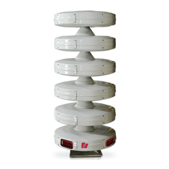
General Description • 360º coverage without sound variation in horizontal planes • Easy servicing through convenient access panels • Anechoic chamber-certified • Optional visual signaling options that enhance the Modulator’s intelligible voice communication and signaling • New models offer steel/concrete pole mounting solution The following is a picture of the Modulator. -
Page 9: Ordering Information
Specifications Ordering Information Contact our Federal Signal sales engineers to design a system that meets your specific requirements. Specify speaker array model number. Each speaker array model must be ordered with a specific corresponding UV and amplifier. Table 2 Ordering Information Speaker Controller UV + 1 UV400... -
Page 10: Table 4 Mod1004B
Specifications Table 4 MOD1004B Number of Active Modules Power 400 watts dB Output 106 dBC at 100 feet (30.48 m) Height of Speaker Array 26.37 inches (66.98 cm) Weight 125 lb (56.70 kg) EPA at 40 feet (12.19 m) 3.30 ft (0.31 m Wind Load (110 mph, 40 feet above ground) 252 lb (114.31 kg) Table 5 MOD2008B... -
Page 11: Table 8 Mod5020B
Specifications Table 8 MOD5020B Number of Active Modules Power 2000 watts dB Output 120 dBC at 100 feet (30.48 m) Height of Speaker Array 80.71 inches (205.00 cm) Weight 385 lb (174.63 kg) EPA at 40 feet (12.19 m) 9.89 ft (0.92 m Wind Load (110 mph, 40 feet above ground) 756 lb (342.92 kg) Table 9 MOD6024B... -
Page 12: Installation
Installation Installation Read and adhere to all safety warnings in this manual before installing the Modulator Series Speaker. Determining a Suitable Location The output level of the sirens is capable of causing permanent hearing damage. To prevent excessive exposure, carefully plan the siren location and post warnings where excessive levels may be encountered. -
Page 13: Installing The Sirens
Installation Assuming a typical 10 dB loss per distance doubled and a 70 dB minimum sound level required to warn a typical urban area, the effective range of a MOD6024B is approximately 3,900 feet. Optimum warning is obtained when the warning signal is at least 10 dB above ambient. Do not expose personnel to sound levels above 123 dBC. -
Page 14: Wooden Pole Mounting
Installation 3. Hand tighten approximately a half turn after gasket engagement. 4. Locate the two (2) wires tie wrapped near the end of the horn throat. Note the label on the back of the drivers and connect the solid wire to terminal 1 and the striped wire to terminal 2 and white jumpers from 1 to 2 as shown in “Figure 6 Driver Connections”... -
Page 15: Figure 3 Typical Wooden Pole-Mounted Installation
Installation Figure 3 Typical Wooden Pole-mounted Installation MOD6024 (SHOWN POLE MOUNTED) CRANE LIFT EYEBOLT 100W DRIVER (4 PER ACTIVE CELL) DRIVER ACCESS DOOR 40' SPEAKER CABLE (LONGER OPTIONAL) (FEDERAL SUPPLIED) CONDUIT & CLAMPS (CUSTOMER SUPPLIED) INSTALL 5/8" LAG BOLTS & SHIMS (CUSTOMER SUPPLIED) AS REQUIRED BETWEEN ANGLE LEGS &... -
Page 16: Steel Pole Mounting
Installation To mount the siren on the Class 2 utility pole using the three-foot-long angle iron legs: 1. Uncrate the siren and remove the nuts that hold the siren on the shipping base. Install drivers if needed. Lift the siren approximately 3-1/2 feet with a crane or hoist. NOTE: To protect the speaker arrays from damage during shipping, all models have been shipped without drivers installed. -
Page 17: Figure 4 Steel Pole Mounting
Installation NOTE: Siren cable is run through the center of the mounting plate through the steel pole. Siren cable can be pre-assembled through center of mounting plate for a no conduit installation. The eyebolt does NOT have sufficient strength to support the combined weight of the siren and a utility pole. -
Page 18: Flat Surface Mounting
Installation Figure 5 Siren Base Plate 18.00 9.00 2.39 3.49 6.23 3.49 2.39 3.49 9.00 4X 1.62 6.23 18.00 Ø23.25 20X Ø0.56 3.49 4X 2.47 4X 4.94 4X 45° 90° 291277A Flat Surface Mounting This installation configuration is practical when the installation site is on a flat roofed building. -
Page 19: Figure 6 Driver Connections
Installation Figure 6 Driver Connections ACTIVE DRIVER - JUMPER DRIVER - SPEAKER CABLE LIGHT MODULE TERMINAL WIRE TERMINAL BOTTOM MOUNT + BOTTOM MOUNT - A1 - 2 A2 - 1 WHT/BRN A2 - 2 WHT/BRN A3 - 2 A3 - 1 A4 - 2 A4 - 1 A1 - 1... -
Page 20: Figure 7 Mod6032B Driver Connections
Installation Figure 7 MOD6032B Driver Connections ACTIVE DRIVER - JUMPER DRIVER - SPEAKER CABLE LIGHT MODULE TERMINAL WIRE TERMINAL BOTTOM MOUNT + BOTTOM MOUNT - A1 - 2 A2 - 1 WHT JUMP WHT/BRN A2 - 2 WHT/BRN A3 - 2 A3 - 1 A4 - 2 A4 - 1... -
Page 21: Installing Lights On The Siren
Installation Installing Lights on the Siren Modulator models can be ordered with optional top lights and/or side lights. If not ordered with the Modulator siren, they can be added later by purchasing the Top Light Kit (Federal Signal part number 191XL-024R) or Side Light Kit (Federal Signal part number MOD-QF-KIT). -
Page 22: Installing The Side Light Kit
Installation Installing the Side Light Kit The Side Light Kit is installed on the bottom (inactive) module. See Figures 9 and 10. To install the Side Light Kit: 1. Replace the standard driver access doors with the side light mounting doors. 2. -
Page 23: Pre-Operation Checkout
Maintenance Pre-Operation Checkout After the siren has been completely installed, perform the following checks before putting the siren into service. The output sound level of a siren is capable of causing severe hearing discomfort or permanent hearing damage. Therefore, ALWAYS wear appropriate hearing protection when performing tests or maintenance on the siren, and post warnings to warn people before they are exposed to excessive sound pressure levels. -
Page 24: Replacing The Driver
Getting Service Replacing the Driver To determine if a driver is defective, refer to the procedure outlined in the installation instruction for the amplifier control unit or remove the speaker circuit from the terminal block and measure the impedance of the circuit. The impedance of each 400 W cell of the siren will measure approximately 4.5 ohms.
Need help?
Do you have a question about the Modulator MOD Series and is the answer not in the manual?
Questions and answers