Table of Contents
Advertisement
Quick Links
Advertisement
Table of Contents

Related Manuals for Federal Signal Corporation MOD Series


Summary of Contents for Federal Signal Corporation MOD Series
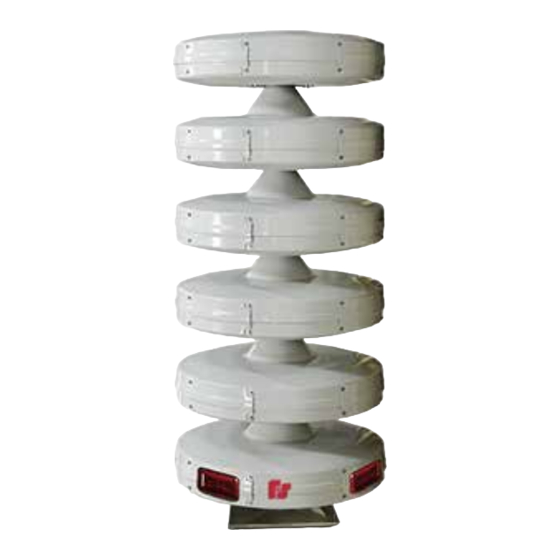
- Page 1 Modulator High-Powered Omni Speaker Model: MOD Series Shown with optional QuadraFlare lights ® Description, Specifications, Installation, and Service Manual 25500059 Rev. A3 1223 Printed in U.S.A. © Copyright 2013-2023 Federal Signal Corporation...
- Page 2 A copy of this limited warranty can also be obtained by written request to Federal Signal Corporation, 2645 Federal Signal Drive, University Park, IL 60484, email to info@fedsig.com or call +1 708-534-3400.
-
Page 3: Table Of Contents
Contents Safety Messages..............................5 General Description ..............................8 Introduction .................................8 Features ................................9 Ordering Information ............................10 Specifications ................................10 Installation ................................13 Determining a Suitable Location ........................13 Installing the Sirens ............................14 Connecting the Driver Wires ........................14 Wooden Pole Mounting .............................15 Steel Pole Mounting ............................17 Flat Surface Mounting ............................19 Driver Connections ............................19 Installing Lights on the Siren ..........................22 Installing the Top Light Kit .........................22... - Page 4 Table 13 Number of Wires and Cable Length per Module .................20 Table 14 Top Light Kit (Model 191XL-024R) ......................22 Table 15 Side Light Kit (Model MOD-QF-KIT) ......................23 Table 16 Replacement Parts ..........................26 Modulator High Powered Omni Speaker (Model MOD Series) Federal Signal www.fedsig.com...
-
Page 5: Safety Messages
Safety Messages Safety Messages It is important to follow all instructions shipped with this product. This device is to be installed by trained personnel who are thoroughly familiar with the country’s electric codes and will follow these guidelines as well as local codes and ordinances, including any state or local noise-control ordinances. - Page 6 Thoroughly discuss all contingency plans with those responsible for warning people in your community, company, or jurisdiction. A well-written contingency plan document is recommended. Modulator High Powered Omni Speaker (Model MOD Series) Federal Signal www.fedsig.com...
- Page 7 Safety Messages Hazard Classification Federal Signal uses signal words to identify the following: DANGER indicates a hazardous situation which, if not avoided, will result in death or serious injury. WARNING indicates a hazardous situation which, if not avoided, could result in death or serious injury.
-
Page 8: General Description
200-2000 Hz. This gives the siren the ability to produce loud and clear voice messages and produce a full spectrum of warning tones. An UltraVoice ® Controller (Model UV) is needed for complete operation. Modulator High Powered Omni Speaker (Model MOD Series) Federal Signal www.fedsig.com... -
Page 9: Features
General Description Features The Modulator Speaker has the following features: • Light-weight, compact design • Uses Federal Signal UltraVoice ® for control and amplification • Excellent frequency response for clear voice reproduction • 360º coverage without sound variation in horizontal planes •... -
Page 10: Ordering Information
The following tables list each MOD model number with its specifications. Each speaker array model must be ordered with a specific corresponding UV and Amplifier. Wind load calculations are for speaker array only. Modulator High Powered Omni Speaker (Model MOD Series) Federal Signal www.fedsig.com... -
Page 11: Table 4 Mod1004B
Specifications Table 4 MOD1004B Number of Active Modules Power 400 watts dB Output 106 dBC at 100 feet (30.48 m) Height of Speaker Array 26.37 inches (66.98 cm) Weight 125 lb (56.70 kg) EPA at 40 feet (12.19 m) 3.30 ft (0.31 m Wind Load (110 mph, 40 feet above ground) 252 lb (114.31 kg) Table 5 MOD2008B... -
Page 12: Table 8 Mod5020B
122.44 inches (311 cm) Weight 580 lb (263.08 kg) EPA at 40 feet (12.19 m) 14.85 ft (1.38 m Wind Load (110 mph, 40 feet above ground) 1134 lb (514.37 kg) Modulator High Powered Omni Speaker (Model MOD Series) Federal Signal www.fedsig.com... -
Page 13: Installation
Installation Installation SOUND HAZARD: The output level of a siren is capable of causing permanent hearing damage. To prevent excessive exposure, carefully plan siren location and post warnings where excessive levels may be encountered. Refer to OSHA 29 CFR 1910.95 for safe exposure limits. Do not expose personnel to sound levels above 123 dBC. -
Page 14: Installing The Sirens
6. Connect the solid wire to terminal 1, the striped wire to terminal 2, and white jumpers from 1 to 2 as shown in “Figure 6 Driver Connections” on page 20. Modulator High Powered Omni Speaker (Model MOD Series) Federal Signal www.fedsig.com... -
Page 15: Wooden Pole Mounting
Installation SOUND REDUCTION HAZARD: Connecting driver wires out of phase may cause severe reduction in sound output, which may result in serious injury or death. Wooden Pole Mounting A typical wooden pole-mounted siren installation is shown in Figure 3. The siren is mounted on a Class 2 utility pole (ANSI-type wooden pole or equivalent) with a minimum horizontal ground stress rating of 3,700 pounds (1678 kg). -
Page 16: Figure 3 Typical Wooden Pole-Mounted Installation
NOTE: DRAWING DEPICTS A TYPICAL INSTALLATION ALWAYS REFER TO LOCAL AND NATIONAL ELECTRICAL BUILDING CODES BEFORE PROCEEDING WITH INSTALLATION. NOTE: CERTAIN SOIL CONDITIONS MAY REQUIRE GUYING FOR THE POLE. 291275B Modulator High Powered Omni Speaker (Model MOD Series) Federal Signal www.fedsig.com... -
Page 17: Steel Pole Mounting
Installation To mount the siren on the Class 2 utility pole using the three-foot-long angle iron legs: Uncrate the siren and remove the nuts that hold the siren on the shipping base. In- stall drivers if needed. Lift the siren approximately 3-1/2 feet with a crane or hoist. NOTE: To protect the speaker arrays from damage during shipping, all models have been shipped without drivers installed. -
Page 18: Figure 4 Steel Pole Mounting
1/16 inch between them, install galvanized or stainless steel shims to even it out. Tighten bolts to 45-46 ft-lb torque. Modulator High Powered Omni Speaker (Model MOD Series) Federal Signal www.fedsig.com... -
Page 19: Flat Surface Mounting
Installation Figure 5 Siren Base Plate 18.00 9.00 2.39 3.49 6.23 3.49 2.39 3.49 9.00 4X 1.62 6.23 18.00 Ø23.25 20X Ø0.56 3.49 4X 2.47 4X 4.94 4X 45° 90° 291277A Flat Surface Mounting This installation configuration is practical when the installation site is on a flat-roofed building. -
Page 20: Figure 6 Driver Connections
42.5 ft 4 are reserved for top or side lights MOD8032B/MOD8032BC 20 wires: 16 are used for driver connections, 44 ft MOD6032B/MOD6032BC 4 are reserved for top or side lights Modulator High Powered Omni Speaker (Model MOD Series) Federal Signal www.fedsig.com... -
Page 21: Figure 7 Mod6032B Driver Connections
Installation Figure 7 MOD6032B Driver Connections ACTIVE DRIVER - JUMPER DRIVER - SPEAKER CABLE LIGHT MODULE TERMINAL WIRE TERMINAL BOTTOM MOUNT + BOTTOM MOUNT - A1 - 2 A2 - 1 WHT JUMP WHT/BRN A2 - 2 WHT/BRN A3 - 2 A3 - 1 A4 - 2 A4 - 1... -
Page 22: Installing Lights On The Siren
Figure 8 Top Light Table 14 Top Light Kit (Model 191XL-024R) Item No. Qty. Description Part Number Light, HAZ, LOC, LED, Red 191XL-024R Modulator High Powered Omni Speaker (Model MOD Series) Federal Signal www.fedsig.com... -
Page 23: Installing The Side Light Kit
Installation Installing the Side Light Kit The Side Light Kit is installed on the bottom (inactive) module. See Figures 9 and 10. To install the Side Light Kit: Replace the standard driver access doors with the side light mounting doors. Wire the four side lights to the two spare wires from the wire harness within the module. -
Page 24: Pre-Operation Checkout
In order to minimize the possibility of siren failure, annual inspection and maintenance are desirable. Perform a driver inspection as described in the next section. Modulator High Powered Omni Speaker (Model MOD Series) Federal Signal www.fedsig.com... -
Page 25: Replacing The Driver
Maintenance Replacing the Driver To determine if a driver is defective, refer to the procedure outlined in the installation instructions for the amplifier control unit or remove the speaker circuit from the terminal block and measure the impedance of the circuit. The impedance of each 400 W cell of the siren will measure approximately 4.5 ohms. -
Page 26: Ordering Parts
Maintenance Ordering Parts To order replacement parts, call customer support. Table 16 Replacement Parts Description Part Number Top Light Kit 191XL-024R Side Light Kit MOD-QF-KIT Driver, 100 watts K8570063A Modulator High Powered Omni Speaker (Model MOD Series) Federal Signal www.fedsig.com... -
Page 27: Getting Technical Support And Service
Getting Technical Support and Service Getting Technical Support and Service For technical support, contact: Federal Signal Technical Support Phone: 800-524-3021 or 708-534-4790 Email: techsupport@fedsig.com www.fedsig.com For customer support, contact: Federal Signal Customer Support Phone: 800-548-7229 or 708-534-3400 extension 367511 Email: customersupport@fedsig.com www.fedsig.com Description, Specifications, Installation, and Service Manual Federal Signal www.fedsig.com... - Page 28 2645 Federal Signal Drive University Park, Illinois 60484 www.fedsig.com Customer Support 800-548-7229 • +1 708 534-3400 Technical Support 800-524-3021 • +1 708 534-4790...
Need help?
Do you have a question about the MOD Series and is the answer not in the manual?
Questions and answers