
Related Manuals for Federal Signal Corporation MODULATOR Series


Summary of Contents for Federal Signal Corporation MODULATOR Series
- Page 1 MODULATOR SERIES SPEAKER ARRAYS INSTALLATION AND MAINTENANCE INSTRUCTIONS 255253G REV. G 12/99...
-
Page 2: Table Of Contents
TABLE OF CONTENTS Paragraph Page SECTION I - CHARACTERISTICS Scope of this Manual …………………………………………………………….……… General ……………………………………………………………………………………. Siren Description …………………………………………………………………………. Signal Description ………………………………………………………………………… Features …………………………………………………………………………………… SECTION II - SPECIFICATIONS Siren ………………………………………………………………………….…………… SECTION III - INSTALLATION Siren Location ……………………………………………………………………………... Siren Installation ………………………………………………………………………... Speaker Connections ……………………………………………………………………. - Page 3 SAFETY NOTICES People’s lives depend on your safe installation, service, and operation of our products. It is important to read, understand and follow all instructions shipped with this product. In addition, listed below are some other important safety instructions and precautions you should follow: INSTALLATION &...
- Page 4 SAFETY NOTICES People’s lives depend on your selection of suitable equipment and installation sites and your safe installation, service, and operation of our products. Follow Federal Emergency Management Agency (FEMA) recommendations. Obtain copies of the latest revision of FEMA’S Outdoor Warning Guide (CPG 1-17) and a Civil Preparedness, Principals of Warning (CPG 1-14) by calling FEMA at (202) 646-3484 or writing to them at 500 C St., South West, Washington, D.C.
- Page 5 LIMITED WARRANTY The Signal Division, Federal Signal Corporation (Federal), warrants each new product to be free from defects in material and workmanship, under normal use and service, for a period of two years on parts replacement and one year on labor from the date of delivery to the first user-purchaser.
-
Page 6: Section I - Characteristics
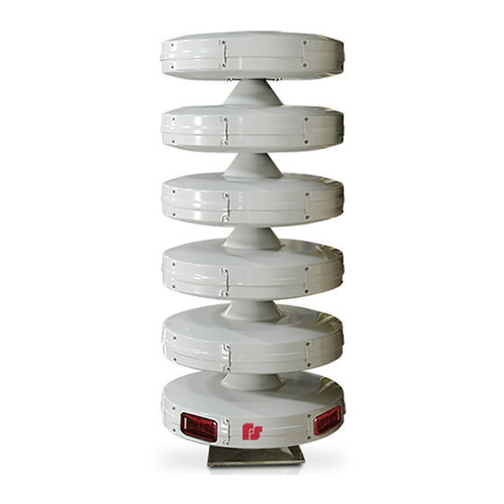
1-3. SIREN DESCRIPTION. Federal Signal’s innovative omnidirectional, electronic Modulator siren series consist of aluminum modules that utilize four 100 watt drivers per module. The Modulator series is available in several models which have the following sound output rating at 100 feet.*... - Page 7 Figure 1-1. Modulator series Outline Drawing...
-
Page 8: Section Ii - Specifications
SECTION II SPECIFICATIONS 2-1. SIREN. Color Weather Guard White II Paint Type TGIC Polyester Powder coat Modular Horn Type Hyperbolic Flare Frequency Response 200 - 2000 Hz. Horizontal Coverage 360 Degree Bottom (non-active) Module* Dimensions 15-1/2 x 44 - 1/2" Diameter MOD1004 Number of Active Modules Power... - Page 9 MOD5020 Number of Active Modules Power 2000 Watts dB output 120 dBC @ 100 feet Height of Speaker Array 125.50" Weight 640 lbs. MOD6024 Number of Active Modules Power 2400 Watts dB output 121 dBC @ 100 feet Height of Speaker Array 146.08"...
-
Page 10: Section Iii - Installation
SECTION III INSTALLATION considerations when choosing a siren DANGER installation site. As the distance from Electrocution severe personal the siren increases, sound level losses injury occur when making accumulate. These losses are a result of weather conditions, the terrain, electrical connections, drilling holes, obstructions in the sound path, the lifting equipment. -
Page 11: Siren Installation
Therefore, for a person to hear a install a siren in almost any situation. warning signal in an industrial area, If the installations in this paragraph the sound level intensity of that signal are not suitable, modification of one of must also be at least 90dB. -
Page 12: Speaker Connections
This is due to the To install a Modulator Series different number of drivers required Siren on a flat roof or other flat for each model. -
Page 13: Pre-Operation Checkout
OBSERVE PROPER POLARITY when making these connections. The striped 3-4. PRE-OPERATION CHECKOUT. wire is common and goes to position 2. After siren been The solid colored wire is signal high completely installed, perform and goes to position 1. Each speaker following checks before putting the connection is color coded. -
Page 16: Section Iv - Service And Maintenance
Before servicing or maintaining, ensure that remote activation can not occur and disconnect power to the siren and its controls. The Modulator Series Siren is designed to require a minimum of maintenance. In addition, experience has shown that all Federal sirens are highly reliable devices. However, if a siren failure does occur, Federal will provide technical assistance with problems that cannot be handled satisfactorily and promptly locally. -
Page 17: Driver Replacement
4-3. DRIVER REPLACEMENT To determine if a driver is bad refer to the procedure outlined in the installation instruction for the amplifier control unit or remove the speaker circuit from the terminal block and measure the impedence of the circuit. The impedence will measure approximately 2.7 ohms. If the reading is higher (5.4 ohms) one driver is bad.
Need help?
Do you have a question about the MODULATOR Series and is the answer not in the manual?
Questions and answers