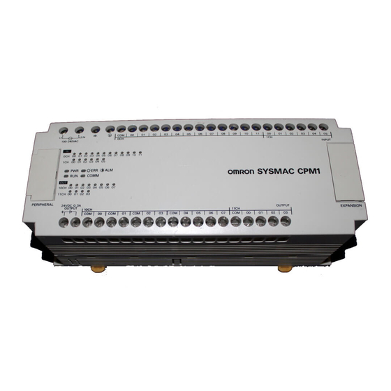
Page 1
CPM1/CPM1A/CPM2A/CPM2C/SRM1(-V2) Programmable Controllers Programming Manual Produced May 1999...
Page 2
OMRON. No patent liability is assumed with respect to the use of the information contained herein. Moreover, because OMRON is constantly striving to improve its high-quality products, the information contained in this manual is subject to change without notice.
Page 6
About this Manual: This manual provides information on programming the CPM1, CPM1A, CPM2A, CPM2C, and SRM1 PCs. The following manuals describe the system configurations and installation of the PCs and provide a basic explanation of operating procedures for the Programming Consoles. They also introduces the ca- pabilities of the SYSMAC Support Software (SSS) and SYSMAC-CPT Support Software.
Page 7
PRECAUTIONS This section provides general precautions for using the Programmable Controller (PC) and related devices. The information contained in this section is important for the safe and reliable application of the Programmable Con- troller. You must read this section and understand the information contained before attempting to set up or operate a PC system.
It is extremely important that a PC and all PC Units be used for the specified purpose and under the specified conditions, especially in applications that can directly or indirectly affect human life. You must consult with your OMRON representative before applying a PC System to the above-mentioned applications.
such problems, external safety measures must be provided to ensure safety in the system. • When the 24-VDC output (service power supply to the PC) is overloaded or short-circuited, the voltage may drop and result in the outputs being turned OFF.
Application Precautions Observe the following precautions when using the PC System. Caution Failure to abide by the following precautions could lead to faulty operation of the PC or the system, or could damage the PC or PC Units. Always heed these pre- cautions.
Page 11
• Be sure that terminal blocks and connectors are connected in the specified direction with the correct polarity. Not doing so may result in malfunction. • Leave the labels attached CPM1 or CPM2A Units when wiring to prevent wir- ing cuttings from entering the Units.
Page 12
• Before touching a Unit, be sure to first touch a grounded metallic object to dis- charge any static built-up. Not doing so may result in malfunction or damage. • Do not touch the Expansion I/O Unit Connecting Cable while the power is be- ing supplied to prevent any malfunction due to static electricity.
Page 13
Start Guide (W332) and User Manual (W333) for SYSMAC-CPT Support Software procedures. If you are not familiar with OMRON PCs or ladder diagram program, you can read 1-1 PC Setup as an overview of the operat- ing parameters available for the CPM1/CPM1A, CPM2A/CPM2C, and SRM1(-V2). You may then want to read Section 5 Memory Areas, Section 6 Ladder-diagram Programming, and related instructions in Section 7 Instruction Set before complet- ing this section.
• RS-232C Port Settings (DM 6645 to DM 6649) Note The RS-232C Port Settings (DM 6645 to DM 6649) are not used in CPM1/CPM1A PCs because these PCs aren’t equipped with an RS-232C port. Errors in the PC Setup If an incorrect PC Setup setting is accessed, a non-fatal error (error code 9B) will be generated, the corresponding error flag (AR 1300 to AR 1302) will be turned ON, and the default setting will be used instead of the incorrect setting.
4) Settings related to communications. This section will explain the settings according to these classifications. The following table shows the settings for CPM1/CPM1A PCs in order. Refer to the page number in the last column for more details on that setting.
Page 16
Section Word(s) Bit(s) Function Page Interrupt Processing (DM 6620 to DM 6639) The following settings are effective after transfer to the PC the next time operation is started. DM 6620 00 to 03 Input constant for IR 00000 to IR 00002 0: 8 ms;...
Page 17
If the power remains off for longer than the backup time of the capacitor, the data may be lost. (For details on the holding time, refer to the CPM1A or CPM1 Operation Manual .)
Page 18
Section 2. Do not set to “05” to “07.” If set to this value, the CPM1/CPM1A will not oper- ate properly and the RUN PC Setup Error Flag (AR 1302 ON) will not turn 3. Retention of IOM Hold Bit (SR 25212) Status If the “IOM Hold Bit Status at Startup”...
Section 1-1-3 CPM2A/CPM2C PC Setup Settings The PC Setup is broadly divided into four categories: 1) Settings related to basic PC operation and I/O processes, 2) Settings related to pulse output functions, 3) Settings related to interrupts, and 4) Settings related to communications. This section will explain the settings according to these classifications.
Page 20
Section Word(s) Bit(s) Function Page DM 6616 00 to 07 Servicing time for RS-232C port (Effective when bits 08 to 15 are set to 01.) 00 to 99 (BCD): Percentage of cycle time used to service RS-232C port. 08 to 15 RS-232C port servicing setting enable 00: 5% of the cycle time 01: Use time in bits 00 to 07.
Page 21
Section Word(s) Bit(s) Function Page DM 6630 to 00 to 15 Not used. DM 6641 High-speed Counter Settings (DM 6640 to DM 6644) The following settings are effective after transfer to the PC the next time operation is started. DM 6640 to 00 to 15 Not used.
Page 22
Section Word(s) Bit(s) Function Page DM 6647 00 to 15 Transmission delay (0000 to 9999 BCD sets a delay of 0 to 99,990 ms.) (Any other setting specifies a delay of 0 ms, causes a non-fatal error, and turns ON AR 1302.) DM 6648 00 to 07...
Page 23
Section Word(s) Bit(s) Function Page Peripheral Port Communications Settings The following settings are effective after transfer to the PC. If the CPM2A CPU Unit’s Communications Switch is ON, communications through the peripheral port are governed by the default settings (all 0) regardless of the settings in DM 6650 through DM 6654. The CPM2A’s Communications Switch setting has no effect on communications with a Programming Console connected to the peripheral port or Support Software set for peripheral bus communications.
Page 24
Section Word(s) Bit(s) Function Page DM 6652 00 to 15 Transmission delay (0000 to 9999 BCD sets a delay of 0 to 99,990 ms.) (Any other setting specifies a delay of 0 ms, causes a non-fatal error, and turns ON AR 1302.) DM 6653 00 to 07...
Section 1-1-4 SRM1(-V2) PC Setup Settings The PC Setup is broadly divided into three categories: 1) Settings related to ba- sic PC operation and I/O processes, 2) Settings related to the cycle time, and 3) Settings related to communications. This section will explain the settings ac- cording to these classifications.
Page 26
Section Word(s) Bit(s) Function Page DM 6618 00 to 07 Cycle monitor time (effective when bits 08 to 15 are set to 01, 02, or 03) 00 to 99 (BCD): Setting (see 08 to 15) 08 to 15 Cycle monitor enable (Setting in 00 to 07 x unit; 99 s max.) 00: 120 ms (setting in bits 00 to 07 disabled) 01: Setting unit: 10 ms 02: Setting unit: 100 ms...
Page 27
Section Word(s) Bit(s) Function Page DM 6649 00 to 07 Start code (RS-232C) 00 to FF (binary) 08 to 15 When bits 12 to 15 of DM 6648 are set to 0: Number of bytes received 00: Default setting (256 bytes) 01 to FF: 1 to 255 bytes When bits 12 to 15 of DM 6648 are set to 1: End code (RS-232C)
Section Word(s) Bit(s) Function Page DM 6654 00 to 07 Start code (effective when bits 08 to 11 of DM6650 are set to 1.) 00: 256 bytes 01 to FF: 1 to 255 bytes 08 to 15 End code When bits 12 to 15 of DM6653 are set to 0: 00: 256 bytes 01 to FF: 1 to 255 bytes When bits 12 to 15 of DM6653 are set to 1:...
CPU Unit for at least 15 minutes. 1-2-3 Program Memory Write-protection In CPM1, CPM1A, CPM2A, and CPM2C PCs, the program memory can be pro- tected by setting bits 00 to 03 of DM 6602 to 0. Bits 04 to 07 determine whether Programming Console messages are displayed in English or Japanese.
Section Note DM 6602 itself can still be changed after the program memory has been write- protected by setting bits 04 to 07 of DM 6602 to 1. 1-2-4 RS-232C Port Servicing Time (CPM2A/CPM2C/SRM1(-V2) Only) The following settings are used to determine the percentage of the cycle time devoted to servicing the RS-232C port.
Section The cycle monitor time is used for checking for extremely long cycle times, as can happen when the program goes into an infinite loop. If the cycle time ex- ceeds the cycle monitor setting, a fatal error (FALS 9F) will be generated. Note 1.
Page 32
07: 64 ms 08: 128 ms The CPM1/CPM1A’s I/O response time is the input time constant (1 ms to 128 ms; default is 8 ms) + the cycle time. Refer to 8-1 CPM1/CPM1A Cycle Time and I/O Response Time for more details.
Battery errors and cycle time overrun errors are non-fatal errors. For details on the error log, refer to Section 9 Troubleshooting. Note The low battery error is applicable to CPM2A/CPM2C only. This digit isn’t used in CPM1/CPM1A/SRM1(-V2) PCs and CPM2C PCs that aren’t equipped with a battery.
SECTION 2 Special Features This section explains special features of the CPM1, CPM1A, CPM2A, CPM2C, and SRM1(-V2). CPM2A/CPM2C Interrupt Functions .........
Section CPM2A/CPM2C Interrupt Functions Types of Interrupts The CPM2A and CPM2C provide the following kinds of interrupt processing. In- terrupts may be disabled temporarily when online editing is performed during operation or STUP(----) is executed to change settings. Interrupt Inputs Interrupt programs are executed when inputs to the CPU Unit’s built-in input points (00003 to 00006*) are turned from OFF to ON.
Section 3. It is not possible to write a subroutine program within an interrupt subroutine. Do not nest an ordinary subroutine program between the SBN(92) and RET(93) instructions. 4. It is not possible to write an interrupt subroutine within an ordinary subrou- tine program.
Page 37
Section Input number Interrupt Subroutine Minimum Interrupt (Note 1) number number input signal response time (Note 2) width 50 µs µ 00003 0.3 ms (from when input turns 00004 ON until program ON until program 00005 execution) execution) 00006 Note 1.
Page 38
Section Procedure for Using Interrupt Inputs Set the interrupt input number. Wire the inputs. Input numbers: 00003 to 00006 PC Setup (DM 6628) Use as interrupt inputs (interrupt input mode or counter mode) Create a ladder diagram program. INT(89): For masking and unmasking interrupt inputs. SBN(92) and RET(93): For creating interrupt subroutines.
Page 39
Section Wiring the Inputs With a CPM2A, wire to the input terminals as shown in the following illustration. Input number 00003: Interrupt input 0 Input number 00004: Interrupt input 1 Input number 00005: Interrupt input 2 Input number 00006: Interrupt input 3 With a CPM2C, wire to the input terminals as shown in the following illustration.
Page 40
Section Instruction Control Operation (@)INT(89) Mask/unmask interrupt Prohibits or permits specified interrupts. inputs Clear interrupt inputs Clears the cause of a prohibited interrupt input. Read current mask Reads the permitted/prohibited status of status an interrupt input. Mask all interrupts Prohibits all interrupts, including interrupt inputs, interval timer interrupts, high-speed counters, etc.
Page 41
Section of the interrupt inputs so that they will not be executed when interrupt inputs are permitted (i.e., when the mask is removed). (@)INT(89) Interrupt control designation (001: Clear interrupt inputs) Fixed at 000. Control data word Specifies/stores 0. Specifies input 00006 (interrupt input 3). Specifies input 00005 (interrupt input 2).
Page 42
Section Unmasking All Interrupts (@)INT(89) Interrupt control designation (200: Unmask all interrupts) Fixed at 000. Fixed at 000. The masking or unmasking all interrupts cannot be executed within an interrupt subroutine. If causes for interrupts occur while all interrupts are masked, the causes will be recorded for each interrupt but the interrupt processing will not be executed.
Section PC Setup DM 6628 Input 00003 is used as an interrupt input. (Inputs 00004 to 00006 are used as ordinary inputs.) Programming ON for 1 cycle at beginning of operation Clears Increment Area (DM 0000). Permits interrupt for interrupt input 0 (input 00003). (89) Always ON Executed when input 00003 turns from OFF to ON.
Page 44
Section The following table shows the relationships between interval timer interrupts and the CPM2A/CPM2C’s other functions. Interval timer interrupts Synchronized pulse control Can be used simultaneously. Interrupt inputs Can be used simultaneously. Interval timer interrupts High-speed counters Can be used simultaneously. Interrupt inputs (counter mode) Can be used simultaneously.
Page 45
Section Scheduled-interrupt Mode Normal program Interrupt program Interval timer interrupt Interval timer operation Start timer In the scheduled-interrupt mode, the timer is reset each time the interrupt pro- gram is called when the set time elapses, and then the interval timer operates again.
Page 46
Section The interval from when STIM(69) is executed until the set time elapses is calcu- lated as follows: (Content of word C ) x (Content of words C + 1) x 0.1 ms (0.5 to 319,968 ms) When a constant is set for C2, that value will be taken as the decrementing counter initial value, and the decrementing time interval will become 10 (1 ms).
Page 47
Section Operation Example One-shot Mode Explanation In this example, the timer is started when the execution condition (00005) turns from OFF to ON. When the time (approx. 1 s) has elapsed, the interrupt subrou- tine is executed one time. When the interrupt subroutine is executed, 1 is added to DM 0000.
Section Scheduled-interrupt Mode Explanation In this example, the timer is started when the execution condition (00005) turns from OFF to ON. Then the interrupt subroutine is executed each time that the set time (approx. 1 s) elapses. Each time the interrupt subroutine is executed, 1 is added to DM 0000.
Page 49
Section High-speed Counter The built-in high-speed counter is a counter based on inputs to the CPU Unit’s built-in points 00000 to 00002. The high-speed counter itself has one point, and it can provide either an incrementing/decrementing or just an incrementing count depending on the mode setting.
Page 50
Section tines can be registered in the table in either the incrementing or decrementing direction. Current count Target values in incrementing direction Target values in decrementing direction Time Match with target value Match with target value during incrementing count during decrementing count Interrupt processing can be executed when the current count matches a target value in either the incrementing or decrementing direction.
Section 2-2-1 Using High-speed Counters The CPM2A/CPM2C’s CPU Unit has one built-in channel for a high-speed counter that can count inputs at a maximum of 20 kHz. Using this in conjunction with the interrupt function enables target value comparison control or range comparison control to be executed without deviating from the cycle time.
Page 52
Section Function Interval timer interrupts Synchronized pulse control Cannot be used simultaneously. Interrupt inputs Can be used simultaneously. Interval timer interrupts Can be used simultaneously. High-speed counters Interrupt inputs (counter mode) Can be used simultaneously. Pulse outputs Can be used simultaneously. Quick-response inputs Can be used simultaneously.
Page 53
Section PC Setup High-speed counter function DM 6642, bits 08 to 15 Count-check interrupt Count Input mode Encoder generated. inputs Differential phase input Pulse + direction input Ladder diagram program Specified subroutine executed Up/down input (when count-check interrupts are used). REGISTER COMPARI- CTBL(63) Increment input...
Page 54
Section Pulse + Direction Input Mode In the pulse + direction input mode, pulse signals and direction signals are input, and the count is incremented or decremented according to the direction signal status. Maximum frequency: 20 kHz Pulse inputs Direction inputs Count 1,000...
Page 55
Section only. If the count is outside of the permissible range, an overflow or underflow will result. The PV will become 0FFFFFFF if an overflow occurs, or FFFFFFFF if an underflow occurs, and the comparison will be stopped. Differential phase input mode Pulse + direction input Overflow (0FFFFFFF)
Page 56
The relationship between the target value comparison count check and the com- parison table is different for the CPM1/CPM1A. Refer to the individual manuals for details. It is not possible to specify more than one comparison direction condition for the same target value in the comparison table.
Page 57
Section Either target value comparison or range comparison can be used for high-speed counter interrupts. If an interrupt is generated during execution of one of the high-speed counter control instructions, i.e., CTBL(63), INI(61), or PRV(62), these instructions will not be executed within the interrupt program. If an interrupt is generated while an instruction controlling the high-speed count- er is being executed in the normal program area, the CTBL(63), INI(61), and PRV(62), instructions will not be executed within the interrupt program.
Page 59
Section Increment Mode Input terminals Input connector 00002: Reset input 00000: Pulse input 00002: Reset input 00000: Pulse input When phase-Z and reset inputs are not used, 00002 can be used as an ordinary input. PC Setup Set the PC Setup areas related to the high-speed counter as follows: High-speed counter usage DM 6642, bits 08 to 15 Input mode...
Page 60
Section Ladder Diagram The following table shows the instructions related to high-speed counter control. Programming Instruction Control Operation (@)CTBL(63) Register target value Registers target value comparison table. comparison table Register range Registers range comparison table. comparison table Register target value Registers target value comparison table comparison table and and starts comparison.
Page 61
Section Register Target Value Comparison Table and Start Comparison (@)CTBL(63) Port specifier (000: High-speed counter) Mode designation (000: Register target value comparison table and start comparison) Beginning word of comparison table Target Value Comparison Table Number of comparisons Number of comparisons 0001 to 0016 BCD Target value 1 (rightmost) Target value (rightmost, leftmost)
Page 62
Section Range Comparison Table Eight range comparison conditions consisting of upper Lower limit 1 (rightmost) and lower limits and subroutine numbers must be set. Lower limit 1 (leftmost) Range comparison Upper and lower limits (rightmost, leftmost) condition 1 Upper limit 1 (rightmost) Register the upper and lower limits.
Page 63
Section Change PV This function changes the high-speed counter PV. (@)INI(61) Port specifier (000: High-speed counter) Control designation (002: Change PV) Beginning word of PV data to change PV data to change (Rightmost and leftmost) Rightmost 4 digits Register the PV data to be changed. Leftmost 4 digits The leftmost digit shows the sign (+/--).
Page 64
Section Read Status This function reads the high-speed counter status, such as whether a compari- son operation is in progress or whether an overflow or underflow has occurred. Using an Instruction (@)PRV(62) Port specifier (000: High-speed counter) Control designation (001: Read status) Word for storing status Overflow/underflow Comparison...
Page 65
Section AR 1100 through AR 1107 are refreshed with every scan, so there may be a dis- crepancy from the exact PV range comparison result at any given time. When the range comparison result is read by executing PRV(62), AR 1100 through AR 1107 are refreshed with the same timing.
Page 66
Section Wiring (CPM2C) Input terminals Blue Rotary encoder Brown Orange White Black Input connector Blue Rotary encoder Brown Orange White Black PC Setup DM 6642 0: Differential phase input 0: Reset by phase-Z signal + software reset 01: Use as high-speed counter...
Page 67
Section Programming ON for 1 cycle at beginning of operation (71) Register target value comparison table and begin comparison (63) High-speed counter Register target value comparison table and begin comparison Beginning word of comparison table Number of comparisons: 5 (92) Target value: Always ON 00010000...
Page 68
Section Range Comparison Explanation In this example, specified interrupt subroutines are executed by matching the high-speed counter’s PV with five range set as a range comparison table. With each interrupt, the data in DM 0000 to DM 0004 is incremented by one. Wiring (CPM2A) Orange E6B2-CWZ6C...
Page 69
Section Wiring (CPM2C) Input terminals Blue Rotary encoder Brown Orange White Black Input connector Blue Rotary encoder Brown Orange White Black PC Setup DM 6642 0: Differential phase input 0: Reset by phase-Z signal + software reset 01: Use as high-speed counter...
Page 70
Section Programming ON for 1 cycle at beginning of operation (71) Register range comparison table and begin comparison (63) High-speed counter Register range comparison table and begin comparison Beginning word of comparison table Lower limit: 9,000 (92) Comparison 1 Always ON Upper limit: 10,000 Comparison 1...
Section 2-2-2 Input Interrupts In Counter Mode The four built-in interrupt inputs in the CPM2A/CPM2C’s CPU Unit can be used in counter mode as inputs of up to 2 kHz. These inputs can be used as either incrementing counters or decrementing counters, triggering an interrupt (i.e., executing an interrupt subroutine) when the count matches the set value.
Page 72
Section Caution Although IORF(97) can be used in interrupt subroutines, you must be careful of the interval between IORF(97) executions. If IORF(97) is executed to frequently, a fatal system error may occur (FALS 9F), stopping operation. The interval be- tween executions of IORF(97) should be at least 1.3 ms + total execution time of the interrupt subroutine.
Page 73
Section Counter (2 kHz) 0 Interrupt generated Interrupt input (counter mode) Interrupt input Specified subroutine executed. (Used only for count-up interrupts.) Ladder diagram program SBN(92) INTERRUPT INT(89) CONTROL instruction Counter (2 kHz) 1 RET(93) Change SV (increment/ decrement) Counter (2 kHz) 2 Counter SV Counter 0 SR 240...
Page 74
Section Selecting Incrementing Either an incrementing or decrementing count can be used with interrupt inputs or Decrementing Count in counter mode. Incrementing Counter Mode As the set value (SV) is refreshed, the count is incremented from 0, and the inter- rupt subroutine is executed when the present value (PV) matches the SV.
Page 75
Section With the CPM2C, wire the input terminals as shown in the following illustration. Input terminals 00004: Input interrupt (counter mode) 1 00003: Input interrupt (counter mode) 0 Input connector 00006: Input interrupt (counter mode) 3 00005: Input interrupt (counter mode) 2 00004: Input interrupt (counter mode) 1 00003: Input interrupt (counter mode) 0 Note Inputs 00006 and 00005 cannot...
Page 76
Section Ladder Diagram The following table shows the instruction operations related to interrupt input Programming (counter mode) control. Instruction Control Operation (@)INT(89) Refresh incrementing Refreshes the counter’s SV and starts the counter SV incrementing count. Refresh decrementing Refreshes the counter’s SV and starts the counter SV decrementing count.
Page 77
Section Starting the Count Operation and Permitting Interrupts Incrementing Counter (@)INT(89) Interrupt control designation (004: Refresh incrementing counter SV) Fixed: 000 Control data word Decrementing Counter (@)INT(89) Interrupt control designation (003: Refresh decrementing counter SV) Fixed: 000 Control data word Specify and store 0 Specify interrupt input (counter mode) 3 Specify interrupt input (counter mode) 2...
Page 78
Section Using Data Areas The high-speed counter’s present value (PV) is stored in words SR 244 to SR 247 as shown below. SR 244 Interrupt input (counter mode) 0 SR 245 Interrupt input (counter mode) 1 SR 246 Interrupt input (counter mode) 2 SR 247 Interrupt input (counter mode) 3 Words SR 244 to SR 247 are refreshed with every scan, so there may be a dis-...
Specifies bit 00003. (Others are masked.) Executed one time when count is up. CPM1/CPM1A Interrupt Functions This section explains the settings and methods for using the CPM1/CPM1A in- terrupt functions. 2-3-1 Types of Interrupts The CPM1/CPM1A has three types of interrupt processing, as outlined below.
Page 80
Section When two interrupts with equal priority are received at the same time, they are executed in the following order: Input interrupt 0 > Input interrupt 1 > Input interrupt 2 > Input interrupt 3 Interval interrupts > High-speed counter interrupts Interrupt Program Observe the following precautions when using interrupt programs: Precautions...
2-3-2 Input Interrupts The 10-pt CPU Units (CPM1-10CDR- and CPM1A-10CDR- ) have two inter- rupt inputs (00003 and 00004). The 20-, 30-, and 40-pt CPU Units (CPM1-20CDR- , CPM1A-20CDR- CPM1-30CDR- (-V1), CPM1A-30CDR- and CPM1A-40CDR- ) have four interrupt inputs (00003 to 00006).
Page 82
Inputs 00003 to 00006 must be set as interrupt inputs in DM 6628 if they are to be used for input interrupts in the CPM1/CPM1A. Set the corresponding digit to 1 if the input is to be used as an interrupt input (input interrupt or counter mode);...
Page 83
Section Input Interrupt Mode When an input interrupt signal is received, the main program is interrupted and the interrupt program is executed immediately, regardless of the point in the cycle in which the interrupt is received. The signal must be ON for 200 µs or more to be detected.
Page 84
Section Program Example When input 00003 (interrupt no. 0) goes ON, operation moves immediately to the interrupt program with subroutine number 000. Inputs for DM 6628 have been set to 0001. 25315 First Cycle Flag ON for 1 cycle @INT(89) Mask/unmask input interrupts.
Page 85
Section 2. With the INT(89) instruction, refresh the Counter Mode set value and enable interrupts. If D bits 0 to 3, which correspond to input interrupts 0 to 3, (@)INT(89) are set to “0,” then the set value will be refreshed and inter- rupts will be permitted.
Section Program Example When input 00003 (interrupt no. 0) goes ON 10 times, operation moves immedi- ately to the interrupt program with subroutine number 000. The following table shows where the counters‘ set values and present values --1 are stored. Inputs for DM 6628 have been set to 0001.
Use the INT(89) instruction to unmask interrupts as follows: (@)INT(89) 2-3-4 Interval Timer Interrupts The CPM1/CPM1A is equipped with one interval timer. When the interval timer times out, the main program is interrupted and the interrupt program is executed immediately, regardless of the point in the cycle.
Page 88
Section 2. When C is entered as a constant: The settings are the same as for the one-shot mode, but interrupts will con- tinue to be repeated at fixed intervals until the operation is stopped. Reading the Timer’s Elapsed Time Use the STIM(69) instruction to read the timer’s elapsed time.
RET(93) 2-3-5 High-speed Counter Interrupts CPM1/CPM1A PCs have a high-speed counter function that can be used in in- crementing mode or up/down mode. The high-speed counter can be combined with input interrupts to perform target value control or zone comparison control that isn’t affected by the PC’s cycle time.
Page 90
01: Counter being used. Count Range The CPM1/CPM1A’s high-speed counter uses linear operation and the count (present value) is stored in SR 248 and SR 249. (The upper four digits are stored in SR 249 and the lower four digits are stored in SR 248.)
Page 91
Section Processing Two types of signals can be input from a pulse encoder. The count mode used for the high-speed counter will depend on the signal type. The count mode and re- set mode are set in DM 6642; these settings become effective when the power is turned on or PC operation is started.
Page 92
Section Phase-Z Signal + Software Reset I/O refresh Common processing, 1 cycle communications servicing, etc. Program Program Program Program Program Program CPU processing execution execution execution execution execution execution 25200 Phase-Z Not reset Not reset Reset Reset Not reset Operation timing Reset Phase-Z signal turns ON when Not reset.
Page 93
The present value of high-speed counter is maintained in SR 248 and SR 249. Controlling High-speed Counter Interrupts 1, 2, 3... 1. Use the CTBL(63) instruction to save the comparison table in the CPM1/CPM1A and begin comparisons. (@)CTBL(63) C: (3 digits BCD) 000:...
Page 94
To start comparisons again, set the second operand to “000” (execute com- parison), and execute the INI(61) instruction. Once a table has been saved, it will be retained in the CPM1/CPM1A during operation (i.e., during program execution) as long as no other table is saved.
Page 95
Section The PV is read when the PRV(62) instruction is actually executed. Changing the PV There are two ways to change the PV of high-speed counter. The first way is to reset it by using the reset methods. (In this case the PV is reset to 0.) The second way is to use the INI(61) instruction.
Page 96
Section Application Example This example shows a program that uses the high-speed counter with phase-dif- (Up/Down Mode) ference inputs in the Up/Down Mode, making comparisons by means of the range comparison method. The comparison conditions (upper/lower limits of the ranges) are stored in the comparison table with the subroutine numbers.
Section The following diagram shows the example ladder program. DM 6642 must be set to 01 0, where is the reset method which can be set to 0 or 1. 25315 (ON for first cycle) CTBL(63) Registers comparison table, range comparison mode DM 0000 First word of the comparison table SBN(92)
Page 98
Section The time from when the STIM(69) instruction is executed until time elapses is calculated as follows: ) × (Content of C + 1) × 0.1 ms = (0.5 to 319,968 ms) (Content of C 2. When C is entered as a constant: The set value of the decrementing counter will equal the specified constant (in ms) and the decrementing time interval will be 10 (1 ms).
Page 99
Section In this example, an interrupt is generated 2.4 ms (0.6 ms × 4) after input 00005 Application Example (One-shot Mode) goes ON; the interrupt executes interrupt subroutine number 23. 25315 First Cycle Flag ON for 1 cycle MOV(21) #0004 Sets the decrementing counter‘s set value to 4.
Section CPM2A/CPM2C Pulse Output Functions The CPM2A/CPM2C has two pulse outputs. By means of a selection in the PC Setup, these outputs can be used as two single-phase outputs without accelera- tion and deceleration, two variable duty ratio pulse outputs, or pulse outputs with trapezoidal acceleration/deceleration (one pulse + direction output and one up/ down pulse output).
Page 101
Section Note 1. With single-phase pulse outputs, pulse outputs 0 and 1 can each be output independently. 2. Pulse outputs can be accelerated or decelerated in units of 10 Hz every 10 3. Actual pulses are affected by the transistor output’s ON response time (20 µs max.) and OFF response time (40 µs max.).
Page 102
Section • Instructions: PULS(65) and SPED(64) • With PULS(65), the number of pulses is set for each point (in independent mode only). • With SPED(64), the output mode and target frequency are set for each point, and pulses are output. Instruction execution: PULS(65) + SPED(64) (Independent mode) Independent mode Number of set pulses...
Page 103
Section Up/Down Pulse Outputs • For CW output: Pulses output from output number 01000 (Word 010, bit 00). • For CCW output: Pulses output from output number 01001 (Word 010, bit 01). 01000 CW operation 01001 CCW operation • Output mode: Continuous and Independent •...
Section 2-5-1 Using Single-phase Pulse Outputs Without Acceleration and Deceleration (Fixed Duty Ratio) Select the pulse output number. Pulse output number 0 or 1 Wire the outputs. Output numbers: 01000 and 01001 PC Setup (DM 6629) PV coordinate system for pulse output numbers 0 and 1 PULS(65): For setting the number of output pulses.
Page 105
Section Wiring the Outputs Wire the CPM2A outputs as shown in the following illustration. (Pulses can be output independently from pulse outputs 0 and 1. Output 01000: Pulse output 0 (single-phase output) Output 01001: Pulse output 1 (single-phase output) Wire the CPM2C outputs as shown in the following illustration. (Pulses can be output independently from pulse outputs 0 and 1.
Page 106
Section The settings will go into effect when the mode is changed (from PROGRAM to MONITOR/RUN) or when the power supply is turned ON to the PC. Ladder Diagram The following table shows the instruction operations related to pulse outputs Programming without acceleration and deceleration (fixed duty ratio).
Page 107
Section Word Bits Name Contents AR 12 12 Pulse output 1 PV overflow/underflow ON: Occurred OFF: Normal Number of pulses set for pulse output 1 ON: Set (by PULS(65)) OFF: Not set Pulse output completed for pulse ON: Completed (by output 1 SPED(64)) OFF: Not completed...
Page 108
Section Change Pulse Output PV Resetting Pulse Output PV This function changes the pulse output present value (PV). The PV can also be cleared by using SR 25204 and SR 25205. (@)INI(61) Port specifier (000: Pulse output 0; 010: Pulse output 1) Control designation (004: Change pulse output PV) Beginning word for PV change data Rightmost 4 digits...
Page 109
Section Using Data Areas As shown in the following illustration, the pulse output PV for pulse output 0 is stored in words 228 and 229, and the pulse output PV for pulse output 1 is stored in words 230 and 231. Pulse Output 0 Pulse Output 1 Word 228...
Page 110
Section Relationship Between Status and Operation Independent Mode (Without Acceleration and Deceleration) Frequency Time PULS(65) execution SPED(64) execution Output in progress Output completed Number of pulses set Continuous Mode Frequency Time SPED(64) execution INI(61) execution Output in progress Output completed Number of pulses set Stopping Output in Independent Mode (Without Acceleration and Deceleration) Frequency...
Page 111
Section Application Examples Positioning Explanation In this example, when the execution condition (00005) turns ON, 100 pulses are output from output 01000 (pulse output 0) at a frequency of 60 Hz. Frequency 60 Hz Number of pulses Execution condition (00005) Wiring Wire the CPM2A to the motor driver as shown in the following illustration.
Page 112
Section Programming 00005 (Execution condition) (13) Detects turning ON of execution condition. PLUS(65) Sets number of pulses. Pulse output 0 Relative pulses DM 0000 Beginning word for pulse Number of pulses: SV data DM 0001 SPED(64) Sets frequency and starts pulse output. Pulse output 0 Independent mode Frequency: 60 Hz...
Page 113
Section Wire the CPM2C to the motor driver as shown in the following illustration. In this case, a CPU Unit with sinking transistor outputs is used. Output connector Motor Driver 24 VDC Note Refer to page operation manual for details on wiring outputs. PC Setup DM 6629 Sets the coordinate system for pulse outputs 0 and 1 as relative.
Section 2-5-2 Using Pulse Outputs With Variable Duty Ratio Select the pulse output number. Pulse output number 0 or 1 Wire the outputs. Output numbers: 01000 and 01001 PWM(----): For setting the frequency and duty ratio. Create a ladder diagram program. INI(61): For stopping pulse outputs.
Page 115
Section Wire the CPM2C outputs as shown in the following illustration. (Pulses can be output independently from pulse outputs 0 and 1. Output connector 01000: Pulse output 0 (single-phase output) 01001: Pulse output 1 (single-phase output) PC Setup Make the following settings in the PC Setup. Word Bits Function...
Page 116
Section The following table shows the words and bits related to pulse outputs with vari- able duty ratio. Word Name Contents AR 11 Pulse output in progress ON: In progress (by SPED(64), for pulse output 0 ACC(----), or PWM(----)) OFF: Stopped AR 12 Pulse output in progress ON: In progress (by SPED(64),...
Page 117
Section Using Data Areas As shown in the following illustration, the pulse output status for pulse output 0 is stored in AR 1115, and the pulse output status for pulse output 1 is stored in AR 1215. AR 11: Pulse output 0 AR 12: Pulse output 1 Pulse output in progress 0: Stopped...
Page 118
Section Wire the CPM2C to the motor driver and thumbwheel switch as shown in the fol- lowing illustration. In this case, a CPU Unit with sinking transistor outputs is used. Input connector Output connector Motor Driver Thumbwheel switch 24 VDC Note Refer to the operation manual for details on wiring.
Section 2-5-3 Using Pulse Outputs With Trapezoidal Acceleration and Deceleration Select the direction control method. Pulse + direction output or up/down pulse output Select the pulse output number. Pulse output number 0 Wire the outputs. Output numbers: 01000 and 01001 PC Setup (DM 6629) PV coordinate system for pulse output number 0 PULS(65): For setting the number of output pulses.
Page 120
Section Selecting the Direction Select the pulse output direction control method according to the type of signal Control Method used. Pulse + Direction Outputs Up/down Pulse Outputs Selecting the Pulse Select pulse output 0. Output Number Output number Pulse output number 01000 01001 Wiring the Outputs...
Page 121
Section PC Setup Make the following settings in the PC Setup. Word Bits Function Setting DM 6629 00 to 03 Pulse 0 PV 0: Relative coordinate system Either 0 or 1 coordinate 1: Absolute coordinate system system DM 6642 08 to 15 High-speed 00: Do not use.
Page 122
Section The following table shows the words and bits related to pulse outputs with trape- zoidal acceleration and deceleration (fixed duty ratio). Word Bits Name Contents Cannot be used as 00 to 15 Pulse output PV 0, rightmost 4 digits work bits even when work bits even when not used as pulse...
Page 123
Section Set Frequency and Start Pulse Outputs Change Frequency These functions set the output mode, the target frequency, the starting frequen- cy, and the acceleration/deceleration rate, and they begin pulse outputs. They can also be used to change the frequency, by accelerating or decelerating at the specified acceleration/deceleration rate, if pulse outputs are already in progress in continuous mode.
Page 124
Section Setting the Frequency and Acceleration/Deceleration, Starting Pulse Out- puts, and Changing the Frequency in Continuous Mode (@)ACC(----) Fixed at 000: Pulse output 0 Output mode designation Beginning word of settings table Output mode Specify the output mode. 010: Up/down pulse output, CW, continuous mode 011: Up/down pulse output, CCW, continuous mode 012: Pulse + direction output, CW, continuous mode 013: Pulse + direction output, CCW, continuous mode...
Page 125
Section Stop Pulse Outputs, Decelerate and Stop Pulse Outputs These functions stop the pulse outputs. Stop Pulse Outputs (@)INI(61) Fixed at 000: Pulse output 0 Control designation (003: Stop pulse outputs) Fixed at 000 Decelerate Stop Pulse Outputs (@)ACC(----) Fixed at 000: Port specifier Mode designation Beginning word of settings table Acceleration/deceleration rate (#0001 to #1000 BCD: 10 Hz to 10 kHz)
Page 126
Section Read Pulse Output Status This function reads the pulse output status. Using an Instruction (@)PRV(62) Fixed at 000: Pulse output 0 Control designation (001: Read pulse output status) Word for storing pulse output status Pulse output status Number of pulses 0: Not set 0: Constant rate 1: Set...
Page 127
Section Continuous Mode with Acceleration and Deceleration 1 Frequency Time ACC(----) execution (1) ACC(----) execution (2) INI(61) execution Output 0 in progress Output 1 in progress Output completion Output status Set number of pulses Continuous Mode with Acceleration and Deceleration 2 Frequency Time ACC(----) execution (Stop)
Page 128
Section Stopping Outputs in Continuous Mode with Acceleration and Deceleration 2 Frequency Time PULS(65) execution ACC(----) execution ACC(----) execution Output 0 in progress Output 1 in progress Output completion Output status Set number of pulses Application Example Positioning Explanation In this example, when the execution condition (00005) turns ON, 1000 pulses are output from output 01000 (pulse output 0) in a trapezoidal acceleration/de- celeration pattern as shown in the following diagram.
Page 129
Section Wire the CPM2C to the motor driver as shown in the following illustration. In this case, a CPU Unit with sinking transistor outputs is used. Output connector Motor Driver 24 VDC Note Refer to the operation manual for details on wiring. PC Setup DM 6629 Sets the coordinate system for pulse output 0 as relative.
Page 130
Section Jogging Explanation In this example, when the execution condition (00005) turns ON, JOG pulses are output at a frequency of 100 Hz from either output 01000 (CW direction) or out- put 01001 (CCW direction). When the execution condition (00005) turns OFF, the output is stopped.
Page 131
Section Note Refer to the operation manual for details on wiring. PC Setup DM 6629 Sets the coordinate system for pulse output 0 as relative. High-speed counter not used. DM 6642 (Set for other than synchronized pulse control.) Programming 00005 (Execution condition) (13) Detects turning ON of execution condition.
Section CPM1A Pulse Output Functions The CPM1A PCs with transistor outputs have a pulse output function capable of outputting a pulse of 20 Hz to 2 kHz (single-phase). Either IR 01000 or IR 01001 can be selected for pulse output, and the pulse output can be set to either the continuous mode, under which the output can be stopped by an instruction, or the independent mode, under which the output is stopped after a preset number of pulses (1 to 16,777,215).
Section 2-6-1 Programming Example in Continuous Mode In this example program, pulse output begins from IR 01000 when input IR 00004 turns ON, and is stopped when input IR 00005 turns ON. SPED(64) can be used to stop pulse output. When using SPED(64) for that pur- pose, specify #0000 (constant or word contents) as the pulse frequency.
Section Beginning Pulse Output With SPED(64), set the bit location for pulse outputs (IR 01000 or IR 01001), the output mode (independent, continuous), and the pulse frequency to begin the pulse output. @SPED(64) P (3 digits BCD) 000: Outputs to IR 01000 010: Outputs to IR 01001 M (3 digits BCD) 000: Independent mode...
Section Synchronized Pulse Control (CPM2A/CPM2C Only) By combining the CPM2A/CPM2C’s high-speed counter function with the pulse output function, the output pulse frequency can be controlled as a specified mul- tiple of the input pulse frequency. Note A CPU Unit with transistor outputs is required in order to use synchronized pulse control, i.e., either a CPM2A- CDT-D or CPM2A- CDT1-D.
Page 136
Section The directions of pulse inputs are all ignored. The frequency of a pulse that has been input is read, without regard to the direction. The following table shows the relationships between synchronized pulse control and the CPM2A’s other functions. Function Synchronized pulse control Synchronized pulse control...
Page 137
Section Using Synchronized Pulse Control Differential phase pulse input mode, pulse + direction input Select the input mode. mode, up/down pulse input mode, increment mode Select the pulse synchronization Input frequency: 10 Hz to 500 Hz; 20 Hz to 1 kHz; 300 Hz to 20 kHz input frequency.
Page 138
Section Selecting the Input Mode Select the differential phase input mode, the pulse + direction input mode, the up/down pulse input mode, or the increment mode. These modes are explained below. Selecting the Pulse Select one of the following as the input frequency range: 10 Hz to 500 Hz, 20 Hz Synchronization Input to 1 kHz, or 300 Hz to 20 kHz.
Page 139
Section Increment Mode In the increment mode, pulse signals are input and the count is incremented with each pulse. Phase-B inputs can be used as ordinary inputs. Pulse inputs 1,000 Nms → Frequency = Wiring the Inputs Input Wiring Wire the CPM2A inputs as shown in the following diagram. Differential Phase Input Mode Up/Down Pulse Input Mode 00000: Phase-A input...
Page 140
Section Wire the CPM2C inputs as shown in the following diagram. Differential Phase Input Mode Up/Down Pulse Input Mode Input connector Input connector 00002: Phase-Z input 00001: CCW input 00001: Phase-B input 00000: Phase-A input 00000: CW input Pulse + Direction Input Mode Increment Mode Input connector Input connector...
Page 141
Section Wire the CPM2C outputs as shown in the following diagram. Output connector 01000: Pulse output 0 01001: Pulse output 1 PC Setup The settings in the PC Setup related to synchronized pulse control are listed in the following table. Word Bits Function...
Page 142
Section The following table shows the words and bits related to synchronized pulse con- trol. Word Bits Name Contents 00 to 15 Input frequency PV, rightmost digits Reads the input frequency PV. 00 to 15 Input frequency PV, leftmost digits ON: Output in progress AR 11 Pulse output in progress for pulse...
Page 143
Section Words 248 and 249 are refreshed with every scan, so there may be a discrepan- cy from the exact PV at any given time. When the PV is read by executing PRV(62), words 248 and 249 are refreshed with the same timing. Read Synchronized Control Status This function reads the synchronized control status.
Page 144
Section Relationship Between Status and Operation Frequency Input pulses Time Frequency Output pulses Time SYNC(----) execution INI(61) execution Output 0 in progress Output 1 in progress Application Example Explanation In this example, when the execution condition (00005) turns ON, synchronized pulse control is started and pulses are output from output 01000 (pulse output 0) according to the pulses input by the high-speed counter.
Page 145
Section Wire the CPM2C as shown in the following illustration. In this case, a CPU Unit with sinking transistor outputs is used. Output connector Input connector Motor Driver Blue Rotary encoder Brown Orange 24 VDC White Black Note For details regarding motor driver wiring to outputs and rotary encoder wiring to inputs, refer to the CPM2A/CPM2C Operation Manual.
Section 2-10 Analog I/O Functions (CPM1/CPM1A/CPM2A Only) Up to 3 Analog I/O Units can be connected to a CPM2A PC to provide analog I/O. One Analog I/O Unit allows 2 analog inputs and 1 analog output. See 3-1 Analog I/O Unit for details.
2-11 Analog Controls The CPM1/CPM1A and CPM2A PCs are equipped with analog controls that au- tomatically transfer the settings on the CPU Unit’s adjustment switches to words in the CPU Unit’s I/O memory. This function is very useful when there are set values that need to be precisely adjusted during operation.
The analog setting for control 0 is in SR 250. The analog setting for control 1 is in SR 251. Note The above diagram shows the CPM1, but the settings are the same for the CPM1A. Caution The analog setting may change with changing temperatures. Do not use the analog adjustment controls for applications that require a precise, fixed setting.
Section 2-11 2-11-2 CPM2A Analog Controls The CPM2A has two analog controls that can be used for a wide range of timer and counter analog settings. As these controls are turned, values from 0 to 200 (BCD) are stored in the SR Area. Use a Phillips-screwdriver to adjust the controls.
2-12 Quick-response Inputs 2-12-1 CPM1/CPM1A Quick-response Inputs The CPM1/CPM1A have quick response inputs that can be used to enable in- putting shorter signals. All 10-point CPU Units have 2 quick-response input terminals and the 20-, 30-, and 40-point CPU Units have 4 quick-response input terminals.
Section 2-12 Word Settings DM 6628 DM 6628 0: Normal input 0: Normal in ut 1: Interrupt input 2: Quick response input 2: Quick-response input (D f (Default setting: 0) DM 6628 Setting for input 00006: Set to 2 Setting for input 00005: Set to 2 Setting for input 00004: Set to 2 Setting for input 00003: Set to 2 Program Example...
Page 152
Section 2-12 Function Interval timer interrupts Synchronized pulse control Can be used simultaneously. Interrupt inputs See note 1. Interval timer interrupts Can be used simultaneously. High-speed counters Can be used simultaneously. Interrupt inputs (counter mode) See note 2. Pulse outputs Can be used simultaneously.
Page 153
Section 2-12 Wiring the Inputs Wire the CPM2A’s inputs as shown in the following diagram. Input 00003: Quick-response input 0 Input 00004: Quick-response input 1 Input 00005: Quick-response input 2 Input 00006: Quick-response input 3 Wire the CPM2C’s inputs as shown in the following diagram. CPU Units with 10 I/O Points Input terminal Input 00004: Quick-response input 1...
Section 2-13 CPU Units with 20 I/O Points Input connector 00006: Quick-response input 3* 00005: Quick-response input 2* 00004: Quick-response input 1 00003: Quick-response input 0 PC Setup To use quick-response inputs with the CPM2A or CPM2C, make the following settings in the System Setup Area (DM 6628) from a Programming Device.
Page 155
Section 2-13 3. The contents of SR 236 through SR 239 (results of the subroutine execu- tion) will be transferred to the four consecutive words beginning with the first output word. 4. MCRO(99) will then be finished. When MCRO(99) is executed, the same instruction pattern can be used as needed simply by changing the first input word or the first output word.
Programming Console or SSS can be done using decimal inputs and mnemonics for the instructions. The procedure to using the Programming Console to input using decimal values is shown in the CPM1 Operation Manual, CPM1A Operation Manual, CPM2A Operation Manual, CPM2C Operation Manual , and SRM1 Master Control Unit Operation Manual .
Section 2-16 2-16 Expansion Instructions (CPM2A/CPM2C/SRM1(-V2) Only) A set of expansion instructions is available for the CPM2A, CPM2C, and SRM1(-V2) to aid in special programming needs. Function codes can be as- signed to up to 18 of the expansion instructions to enable using them in pro- grams.
Section 2-16 2-16-1 CPM2A/CPM2C Expansion Instructions The following 18 function codes can be used for expansion instructions: 17, 18, 19, 47, 48, 58, 59, 60, 61, 62, 63, 64, 65, 66, 67, 68, 69, and 89. The function code assignments can be changed with a Programming Console or the Support Software.
Section 2-17 2-16-2 SRM1(-V2) Expansion Instructions The following 18 function codes can be used for expansion instructions: 17, 18, 19, 47, 48, 58, 59, 60, 61, 62, 63, 64, 65, 66, 67, 68, 69, and 89. The function code assignments can be changed with a Programming Console or the Support Software.
Section 2-17 2-17-2 Setting the Time To set the time, use a programming device as follows: Setting Everything 1, 2, 3... 1. Turn ON AR 2114 (Clock Stop Bit) to stop the clock and allow AR 18 through AR 21 to be overwritten. 2.
SECTION 3 Using Expansion Units This section describes how to use the CPM1A-MAD01 Analog I/O Unit and the CPM1A-SRT21 CompoBus/S I/O Link Unit. Analog I/O Units ............CompoBus/S I/O Link Unit .
Section Analog I/O Units A maximum of 3 Expansion Units, including CPM1A-MAD01 Analog I/O Units, can be connected to a CPM2A PC. One Analog I/O Unit allows 2 analog inputs and 1 analog output. With the maximum of 3 Analog I/O Units connected, 6 in- puts and 3 outputs of analog I/O are possible.
Page 164
Section Note 1. With analog outputs it is possible to use both voltage outputs and current outputs at the same time. In this case however, the total output current must not exceed 21 mA. 2. The conversion time is the total time for 2 analog inputs and 1 analog output. Analog I/O Signal Range Analog Input Signal Range 0 to 10 V inputs...
Page 165
Section Analog Output Signal Range 0 to 10 V outputs and --10 to +10 V outputs Set value Set value 4 to 20 mA outputs Set value Using Analog I/O Analog inputs: 0 to 10 V, 1 to 5 V, or 4 to 20 mA Set the I/O range Analog outputs: 0 to 10 V, --10 to +10 V, or 4 to 20 mA...
Page 166
Section Analog Inputs CPU Unit Analog I/O Unit Ladder program (n + 1) words Range code Analog input 1 (m + 1) words (21) MOVE instruction conversion value Analog input 2 (m + 2) words Writes the range code. conversion value Reads the conversion value.
Page 167
Section Setting I/O Signal Range The I/O signal range is set by wiring the I/O terminal and by writing the range code to the Analog I/O Unit’s output word. I/O Terminal Arrangement Note When using current inputs, short terminal V IN1 with I IN1 and terminal V IN2 with I IN2.
Page 168
Section Once the range code has been set it is not possible to change the setting while power is being supplied to the CPM2A. To change the I/O range, turn the CPM2A OFF then ON again. Note If a range code other than those specified in the above table is written to n+1, the range code will not be received by the Analog I/O Unit and analog I/O conversion will not start.
Page 169
Section Wiring Analog I/O Devices Analog Input Wiring 2-core shielded Analog I/O Unit twisted-pair cable Analog output 250 Ω device voltage output 10 kΩ Analog 250 Ω output device current output 10 kΩ Analog Output Wiring Voltage Outputs 2-core shielded Analog I/O Unit twisted-pair cable Analog...
Page 170
Section Ladder Program Specifying the Range Code Specify the I/O signal range by writing the range code to the Analog I/O Unit’s output word from the ladder program in the first cycle of program execution. The Analog I/O Unit will start to convert analog I/O values once the range code has been specified.
Page 171
Section Writing Analog Output Set Values A ladder program can be used to write data to the output word where the set val- ue is stored. The output word will be “n+1” when “n” is the last output word allo- cated to the CPU Unit or previous Expansion Unit.
Section Analog I/O Settings Input 1 signal range: 0 to 10 V Input 2 signal range: 4 to 20 mA Output signal range: 0 to 10 V Range Code Setting: FF04 IR 012 Range code: FF04 Program SR 25135 (First Cycle ON Flag) (21) Writes the range code (FF04) to the Unit.
Page 173
Section From the standpoint of the CPU Unit, the 8 input bits and 8 output bits allocated to the CompoBus/S I/O Link Unit are identical to input and output bits allocated to Expansion I/O Units even though the CompoBus/S I/O Link Unit does not control actual inputs and outputs.
Page 174
Section Connecting the Connect the CompoBus/S I/O Link Unit to the CPU Unit. Only one CompoBus/S CompoBus/S I/O Link I/O Link can be connected. When other Expansion Units are also connected, Unit they can be connected in any order from the CPU Unit. CompoBus/S I/O CPU Unit Link Unit...
Page 175
Section The 8 bits of I/O data are not always transmitted simultaneously. In other words, 8 bits of data transmitted from the Master CPU Unit at the same time will not al- ways reach the CPM2A CPU Unit simultaneously, and 8 bits of data transmitted from the CPM2A at the same time will not always reach the Master CPU Unit simultaneously.
Page 176
Section Wiring the CompoBus/S Wire the CompoBus/S communications path as shown in the following diagram. Communications Path These terminals are not used. They can however be used as communications NC (BS+) power supply relay terminals. NC (BS--) (BS +) (BS - -) Connect a CompoBus/S Communications Cable.
SECTION 4 Communications Functions This section describes how to use the communications functions provided in the CPM1, CPM1A, CPM2A, CPM2C, and SRM1(-V2) PCs. Introduction .............
Link Communications in the CPM1A Operation Manual for more details. One-to-one PC Link A data link can be created with a data area in another CPM1, CPM1A, CPM2A, CPM2C, CQM1, or C200HS PC. An RS-232C Adapter is used to make the 1:1 connection.
The CPM1/CPM1A supports C-mode commands only. For details on Host Link communications, refer to 4-5 Host Link Commands. PC Setup Settings The CPM1/CPM1A’s peripheral port settings must be set properly in order to use the Host Link communications, as shown in the following table. Word...
Node number: Example Program This example shows a BASIC program that reads the status of the CPM1’s in- puts in IR 000. For more details, refer to 4-5 Host Link Commands. An FCS (frame check sequence) check isn’t performed on the received re- sponse data in this program.
1. If an improper setting is used, a non-fatal error will occur, AR 1302 will be turned ON, and the default setting (0 or 00) will be used. 2. For information on the NT Link settings for another OMRON PC, refer to that PC’s Operation Manual.
Page 182
LR15 Limitations of 1:1 PC Links Only the 16 LR words from LR 00 to LR 15 can be linked in the CPM1/CPM1A, so with a CPM1/CPM1A use only those 16 words in the CQM1 or C200HS when making a 1:1 PC Link with one of those PCs.
Section Example Program This example shows ladder programs that copy the status of IR 000 in each CPM1/CPM1A to SR 200 in the other CPM1/CPM1A. Program in the Master Program in the Slave 25313 (Always ON) 25313 (Always ON) MOV(21)
Page 184
Note When connecting to the peripheral port, an RS-232C Adapter or computer connection cable (CQM1-CIF01 or CQM1-CIF02) is necessary. One-to-one CPM2C Communications OMRON Programmable Terminal CPM2C RS-232C connection* CPM2C RS-232C connection* Note *When connecting to the peripheral port, an RS-232C Adapter or computer...
Page 185
Section 1:N CPM2A Communications B500-AL004 Link Adapter CPM2A RS-232C CPM2A peripheral port connection port connection NT-AL001 RS-232C/RS-422 CPM1-CIF01 RS-422 Adapter Conversion Adapter 1:N CPM2C Communications B500-AL004 Link Adapter CPM2C CPM2C CPM2C (RS-232C connection) (peripheral connection) (peripheral connection) NT-AL001 RS-232C/RS-422 CPM1-CIF01 RS-422 Adapter...
Page 186
Section Frame Transmission and Reception In Host Link communications, the host computer ordinarily has the transmission right first and initiates the communications. The CPM2A/CPM2C then automati- cally sends a response. Commands and responses are exchanged in the order shown in the illustration below.
Page 187
Section Command and Response Formats This section explains the formats for the commands and responses that are ex- changed in Host Link communications. Command Format When transmitting a command from the host computer, prepare the command data in the format shown below. ↵...
Page 188
Section Dividing Commands As each frame is transmitted by the host computer, the computer waits for the delimiter to be transmitted from the CPM2A/CPM2C. After the delimiter has been transmitted, the next frame will then be sent. This procedure is repeated until the entire command has been transmitted.
Page 189
Section Precautions for Long When dividing commands such as WR, WL, WC, or WD that execute write op- Transmissions erations, be careful not to divide into separate frames data that is to be written into a single word. As shown in the illustration below, be sure to divide frames so that they coincide with the divisions between words.
Page 190
Section Example Program for This example shows a BASIC subroutine program for executing an FCS check on a frame received by the host computer. Normal reception data includes the FCS, delimiter or terminator, and so on. When an error occurs in transmission, however the FCS or some other data may not be included.
Page 191
Section Commands Header CPM2A/CPM2C Operating Mode Name Page code MONITOR PROGRAM Valid Valid Valid IR/WR/SR AREA READ Valid Valid Valid LR AREA READ Valid Valid Valid HR AREA READ Valid Valid Valid TC PV READ Valid Valid Valid TC STATUS READ Valid Valid Valid...
Page 192
Section Response Codes Contents Probable cause Corrective measures code Normal completion Not executable in RUN mode The command that was sent can- Check the relation between the not be executed when the PC is in command and the PC mode. RUN mode.
Page 193
Section Communications Switch The CPM2A’s communications are controlled by the communications switch on Setting the front of the CPU Unit and the CPM2C’s communications are controlled by the DIP switch on the front of the CPU Unit. CPM2A Communications Switch Setting When the communications switch is set to OFF, communications through the pe- ripheral port and RS-232C port are governed by the settings in the PC Setup.
Page 194
According to RS-232C CTS control (5: OFF, 6: ON) The RS-232C port with the NT-AL001 RS-232C/RS-422 Conversion Adapter and the RS-232C port of the CPM2A/CPM2C or CPM1-CIF01 RS-232C Adapter are connected as shown in the following diagram when there is no CTS control on the RS-232C port.
Page 195
Section and CS1W-CN118 connecting cables can be used in place of the RS-232C Adapter. NT-AL001 RS-232C/RS-422 RS-232C port Conversion Adapter Signal Pin No. Signal Pin No. Hood Note Do not connect external devices other than the NT-AL001 Conversion Adapter to the 5 VDC power supply of pin number 6 on the CPM2A/CPM2C’s RS-232C port.
Page 196
Section Word Function Setting DM 6648 00 to 07 00 to 31 (BCD): Node number (Host Link) 00 to 31 (Other settings will cause a non-fatal error, the default setting (00) will be used, and AR 1302 will turn ON.) 08 to 11 Start code enable (RS-232C) 0: Disable;...
Page 197
Section Word Function Setting DM 6653 00 to 07 Node number (Host Link) 00 to 31 00 to 31 (BCD) (Other settings will cause a non-fatal error, the default setting (03) will be used, and AR 1302 will turn ON.) 08 to 11 Start code enable (Peripheral port) 0: Disable...
Section The transmitted Host Link frame will be as shown in the following diagram. Converted to ASCII. N bytes ↵ Data (ASCII) Node No. In the following program example TXD(48) is used to transmit data from an RS-232C port to a host computer. If AR 0805 (the RS-232C Transmit Ready Flag) is ON when IR 00100 turns ON, the ten bytes of data (DM 0100 to DM 0104) will be transmitted to the host computer, leftmost bytes first.
Page 200
RS-232C devices Bar code reader Serial printer Other Note *A CPM1-CIF01 RS-232C Adapter can also be used for no-protocol commu- nications through the peripheral port. Transmission Data Configuration When no-protocol communications are used, TXD(48) is used to send data and RXD(47) to receive data.
Page 201
Section No Start or End Code: Data (Specified No. of bytes) Only a Start Code: Data (Specified No. of bytes) Only an End Code: Data (256 bytes max.) Both a Start and End Code: Data (256 bytes max.) End Code of CR, LF: Data (256 bytes max.) Start Code 00-FF/End Code CR,LF: Data (256 bytes max.)
Page 202
Section Application Procedure Setting the Communications switch Set the CPM2A CPU Unit’s communications switch or the CPM2C CPU Unit’s DIP switch. Connecting the cables Make the RS-232C connection with the serial device. Ladder program Communications Switch The CPM2A’s communications are controlled by the communications switch on Setting the front of the CPU Unit and the CPM2C’s communications are controlled by the DIP switch on the front of the CPU Unit.
Page 203
This section describes RS-232C connections. The RS-232C port on the serial device and the RS-232C port of the CPM2A/ CPM2C or CPM1-CIF01 RS-232C Adapter are connected as shown in the fol- lowing diagram. With the CPM2C, the CPM2C-CN111 and CS1W-CN118 con- necting cables can be used in place of the RS-232C Adapter.
Page 204
Section Settings for RS-232C Port Word Function Setting DM 6645 00 to 03 Port settings As required 0: Standard (1 start bit, 7-bit data, 2 stop bits, even parity, 9,600 bps) 1: Settings in DM 6646 (Other settings will cause a non-fatal error, the default setting will be used, and AR 1302 will turn ON.) 04 to07 CTS control settings...
Page 205
Section Settings for Peripheral Port Word Function Setting DM 6650 00 to 03 Port settings As required 0: Standard (1 start bit, 7-bit data, 2 stop bits, even parity, 9,600 bps) 1: Settings in DM 6651 (Other settings will cause a non-fatal error, the default setting (0) will be used, and AR 1302 will turn ON.) 04 to 11 Not used...
Page 206
Section Program The following instructions are used in no-protocol communications. Mnemonic Control Contents (@)TXD(48) Communications Reads data from I/O memory and transmits it in port output the specified frame format (the start and end codes can be enabled/disabled). (@)RXD(47) Communications Receives data in the specified frame format (the port input start and end codes can be enabled/disabled)
Page 207
Section No-protocol Data Reception RXD(47) is used to receive data from RS-232C devices. (@)RXD(47) D: Leading address for storing reception data C: Control data N: Number of bytes to receive (BCD: 0001 to 0256) Storage order 0: Leftmost bytes first 1: Rightmost bytes first Communications port 0: RS-232C port 1: Peripheral port The following program example is for no-protocol communications conducted...
RON Programmable Terminal. There is no need for a communications program on the PC. The NT Link can be used with an RS-232C port. CPM2A Connection CPM2A CPU Unit RS-232C cable OMRON Programmable Terminal RS-232C port CPM2C 1:1 NT Link Connection RS-232C port...
Page 209
Section CPM2A Communications Switch Setting Turn OFF the communications switch when using 1:1 NT Link communications. One-to-one NT Link communications will not be possible if the communications switch is ON. Communications switch RS-232C port CPM2C DIP Switch Settings Turn OFF pin 1 of the DIP switch when using 1:1 NT Link communications so that communications through the RS-232C port are governed by the settings in the PC Setup (DM 6645 to DM 6649).
(Other settings will cause a non-fatal error, the Host Link setting will be used, and AR 1302 will turn ON.) For information on the 1:1 NT Link settings of an OMRON Programmable Termi- nal, refer to that PT’s Operation Manual.
Page 211
Section One-to-one PC Link between two CPM2A PCs CPM2A CPU Unit CPM2A CPU Unit RS-232C port RS-232C port Master Slave Link bits Link bits LR00 LR00 Write Read Write Read area area LR07 LR07 LR08 LR08 Read Write Read Write area area LR15...
Page 212
Section One-to-one PC Link communications will not be possible if the communications switch is ON. Communications switch RS-232C port CPM2C DIP Switch Settings Turn OFF pin 1 of the DIP switch when using 1:1 PC Link communications so that communications through the RS-232C port are governed by the settings in the PC Setup (DM 6645 to DM 6649).
(Other settings will cause a non-fatal error, the Host Link setting will be used, and AR 1302 will turn ON.) For information on the 1:1 PC Link settings of another OMRON PC, refer to that PC’s Operation Manual. Connecting the Cables This section describes the RS-232C connection.
Page 214
Section mands. The SRM1(-V2) supports C-mode commands only. For details on Host Link communications, refer to 4-5 Host Link Commands. PC Setup Settings The SRM1(-V2)’s peripheral port and RS-232C port settings must be set proper- ly in order to use the Host Link communications, as shown in the following table. Word Function Setting...
Page 215
Section Word Function Setting DM 6654 00 to 07 Start code (effective when bits 08 to 11 of DM6650 are set to 1.) 00: 256 bytes 01 to FF: 1 to 255 bytes 08 to 15 End code (no-protocol) When bits 12 to 15 of DM6653 are set to 0: 00: 256 bytes 01 to FF: 1 to 255 bytes When bits 12 to 15 of DM6653 are set to 1:...
Page 216
Section Word Function Setting DM 6648 00 to 07 Node number (Host Link, effective when bits 12 to 15 of DM 6645 are set to 0.) 00 to 31 00 to 31 (BCD) 08 to 11 Start code enable (RS-232C, effective when bits 12 to 15 of DM 6645 are set to 1.) 0: Disable;...
Section Example Program This example shows a BASIC program that reads the status of the SRM1(-V2)’s inputs in IR 000. For more details, refer to 4-5 Host Link Commands. An FCS (frame check sequence) check isn’t performed on the received re- sponse data in this program.
Page 218
Section 2. Use the TXD(48) instruction to transmit the data. (@)TXD(48) S: Leading word no. of data to be transmitted C: Control data N: Number of bytes to be transmitted (4 digits BCD), 0000 to 0256 From the time this instruction is executed until the data transmission is complete, AR 0805 ( or AR0813 for the peripheral port) will remain OFF.
Page 219
Section The start code and end code are not included in AR 09 or AR 10 (number of bytes received). The data will be as follows: “31323132313231323132CR LF” Peripheral Port Settings When the peripheral port is used to conduct no-protocol communications, the following settings must be made from the Programming Device to DM 6650 to DM 6653 in the SRM1(-V2).
Page 220
Section Word Function Setting DM 6654 00 to 07 Start code (effective when bits 08 to 11 of DM6650 are set to 1.) As re- 00: 256 bytes quired 01 to FF: 1 to 255 bytes 08 to 15 End code (no-protocol) As re- quired When bits 12 to 15 of DM6653 are set to 0:...
Page 221
Section Word Function Setting DM 6647 00 to 15 Transmission delay (Host Link) As re- 0000 to 9999 (BCD): Set in units of 10 ms, e.g., setting of 0001 equals 10 ms quired DM 6648 00 to 07 Node number (Host Link, effective when bits 12 to 15 of DM 6645 are set to 0.) As re- 00 to 31 (BCD) quired...
Page 222
Section 2. When there are several start and end codes, the first part of each will be ef- fective. 3. When the end code duplicates the transmission data and the transmission is stopped part way through, use CR or LF as the end code. 4.
Page 223
1. If an improper setting is used, a non-fatal error will occur, AR 1302 will be turned ON, and the default setting (0 or 00) will be used. 2. For information on the NT Link settings for another OMRON PC, refer to that PC’s Operation Manual.
Page 224
1. If an improper setting is used, a non-fatal error will occur, AR 1302 will be turned ON, and the default setting (0 or 00) will be used. 2. For information on 1:N NT Link settings for OMRON PTs, refer to the PT’s Operation Manual.
Page 225
Section 4-4-5 One-to-one PC Link Communications In a 1:1 PC Link, an SRM1 is linked to another SRM1, a CPM1/CPM1A, CQM1, C200HS, or C200HX/HG/HE PC through a standard RS-232C cable. One of the PCs will serve as the master and the other as the slave. The 1:1 PC Link can connect up to 256 bits (LR 0000 to LR 1515) in the two PCs.
Section 2. For information on the 1:1 PC Link settings for another OMRON PC, refer to that PC’s Operation Manual. 3. If an out-of-range value is set, the following communications conditions will result. In that case, reset the value so that it is within the permissible range.
1. Words 0050 to 0199 cannot be specified in CPM2A/CPM2C PCs and words 0020 to 0199 cannot be specified in CPM1/CPM1A/SRM1(-V2) PCs. If an attempt to read any of these words is made, a response of 0000 will be re- turned.
No. of timers/counters Terminator code Note 1. Beginning T/C: 0000 to 0255 in CPM2A/CPM2C PCs, 0000 to 0127 in CPM1/CPM1A/SRM1(-V2) PCs 2. No. of T/Cs: 0001 to 0256 in CPM2A/CPM2C PCs, 0001 to 0128 in CPM1/CPM1A/SRM1(-V2) PCs Response Format An end code of 00 indicates normal completion.
Read data (for number of words read) Note 1. Words DM 1024 to DM 6143 in CPM1/CPM1A PCs and words DM 2048 to DM 6143 in CPM2A/CPM2C/SRM1(-V2) PCs cannot be specified. If an at- tempt to read any of these words is made, a response of 0000 will be re- turned.
Page 230
Note Words 0050 to 0199 cannot be specified in CPM2A/CPM2C PCs and words 0020 to 0199 cannot be specified in CPM1/CPM1A/SRM1(-V2) PCs. If an at- tempt is made to write to any of these words, the writing operation will not be executed and normal completion occurs.
Section 4-5-9 LR AREA WRITE - - - - WL Writes data to the LR area, starting from the specified word. Writing is done word by word. Command Format ↵ x 10 x 10 x 10 x 10 x 10 x 10 x 16 x 16...
If, for exam- ple, 126 is specified as the beginning word for writing in a CPM1 PC, and three words of data are specified, then 128 will become the last word for writ- ing data, and the command will not be executed because TC 128 is beyond area boundary.
If, for example, 126 is specified as the beginning word for writing in a CPM1 PC, and three words of data are specified, then 128 will become the last word for writing data, and the command will not be executed because TC 128 is beyond area boundary.
If, for example, 12 is specified as the beginning word for writing in a CPM1 PC, and five words of data are specified, then 16 will become the last word for writing data, and the com- mand will not be executed because AR 16 is beyond the writable range.
Program Name TC number* Terminator code address Note TC number: 0000 to 0255 in CPM2A/CPM2C PCs and 0000 to 0127 in CPM1/CPM1A/SRM1(-V2) PCs Response Format An end code of 00 indicates normal completion. ↵ x 10 x 10 x 16...
SV is stored or the constant SV is returned to “SV.” Operand Constant or word address Classification OP1 OP2 CPM2A/ CPM1 PCs CPM2C PCs (Space) IR or SR 0000 to 0049 0000 to 0019 0200 to 0255 0200 to 0255...
10 x 10 x 10 Operand Terminator Note TC number: 0000 to 0255 in CPM2A/CPM2C PCs and 0000 to 0127 in CPM1/CPM1A/SRM1(-V2) PCs Response Format An end code of 00 indicates normal completion. ↵ x 10 x 10 x 16 x 16 Node no.
In “SV,” specify either the word address where the SV is stored or the constant SV. Operand Classification Constant or word address CPM2A/ CPM1/CPM1A/ CPM2C PCs SRM1(-V2) PCs (Space) IR or SR 0000 to 0049 0000 to 0019...
Section Parameters Status Data, Message (Response) “Status data” consists of four digits (two bytes) hexadecimal. The leftmost byte indicates CPU Unit operation mode, and the rightmost byte indicates the size of the program area. x 16 x 16 15 14 13 12 Operation mode 1: Fatal error generated PROGRAM mode...
Section Parameters Mode Data (Command) “Mode data” consists of two digits (one byte) hexadecimal. With the leftmost two bits, specify the PC operating mode. Set all of the remaining bits to “0.” x 16 x 16 Operation mode PROGRAM mode MONITOR mode This area is different RUN mode...
Page 241
Section CPM1/CPM1A/CPM2A/CPM2C PCs 1st word x 16 x 16 x 16 x 16 15 14 13 12 ON: Battery alarm (F7) ON: System error (FAL) ON: Memory error (Error code F1) ON: I/O bus error (Error code C0) ON: No end instruction error (FALS)
“Bit” the number of the bit that is to be forced set. Name Classification Word address setting range OP1 OP2 CPM2A/ CPM1/ CPM1A/ CPM2C PCs SRM1(-V2) PCs (Space) IR or SR 0000 to 0049 0000 to 0019...
“Bit” the number of the bit that is to be forced reset. Name Word address setting range Classification OP1 OP2 CPM2A/ CPM1/CPM1A CPM2C PCs /SRM1(-V2) (Space) IR or SR 0000 to 0049 0000 to 0019...
Page 244
Name Word address setting range Classification OP1 OP2 CPM2A/CPM2C CPM1/CPM1A/ SRM1(-V2) PCs (Space) IR or SR 0000 to 0049 0000 to 0019 0200 to 0252 0200 to 0252...
Model Code “Model code” indicates the PC model in two digits hexadecimal. Model code Model C250 C500 C120 C2000 C1000H C2000H/CQM1/CPM2A/CPM2C/CPM1/CPM1A/SRM1(-V2) C20H/C28H/C40H/C200H/C200HS CV500 CV1000 CV2000 CVM1-CPU01-E CVM1-CPU11-E CVM1-CPU21-E 4-5-27 TEST- - - - TS Returns, unaltered, one block of data transmitted from the host computer.
Section Response Format An end code of 00 indicates normal completion. ↵ x 10 x 10 122 characters max. Node no. Header Characters Terminator code Parameters Characters (Command, Response) For the command, this setting specifies any characters other than the carriage return (CHR$(13)).
Section 4-5-30 COMPOUND COMMAND - - - - QQ Registers at the PC all of the bits, words, and timers/counters that are to be read, and reads the status of all of them as a batch. Registering Read Information Register the information on all of the bits, words, and timers/counters that are to be read.
Page 248
BCD, and the data format is specified in two digits BCD. Read word Area Read data Read area Data format classification CPM2A/ CPM1/ CPM2C PCs CPM1A/ SRM1(-V2) IR or SR C I O (S) 0000 to 0049 0000 to 0019...
Section Response Format An end code of 00 indicates normal completion. x 10 x 10 x 16 x 16 x 10 x 10 x 10 x 10 Data break Node no. Header Sub-header End code Timer/counter code code If PV is specified the status of the Completion Flag is also returned.
Section Response Format An end code of 00 indicates normal completion. ↵ Data specified in TXD(48) x 10 x 10 Terminator Node no. Header Characters code (122 max.) Parameters Characters (Response) This is the data specified in TXD(48) that has been converted to ASCII. 4-5-34 Undefined Command - - - - IC This response is returned if the header code of a command cannot be decoded.
AR1314 will turn ON. (This flag turns ON when data can no longer be retained by the built-in capacitor.) Refer to 2-1-2 Characteristics in the CPM1 and CPM1A Operation Manual for a graph showing the backup time vs. temperature.
Page 253
I/O. 5-1-3 SR Area These bits mainly serve as flags related to CPM1/CPM1A operation or contain present and set values for various functions. For details on the various bit func- tions, refer to relevant sections in this manual or to Appendix C Memory Areas .
Page 254
5-1-9 DM Area DM area data is accessed in word units only. The contents of the DM area are retained even after the CPM1/CPM1A power supply has been turned off or when operation begins or stops. DM words DM 0000 through DM 0999, DM 1022, and DM 1023 can be used freely in the program;...
Section CPM2A/CPM2C Memory Area Functions 5-2-1 Memory Area Structure The following memory areas can be used with the CPM2A/CPM2C. Data area Words Bits Function IR area Input area IR 000 to IR 009 IR 00000 to IR 00915 These bits can be allocated to the external I/O terminals.
Page 256
Section Note When all of the bits in a word are not used as input bits, the unused bits are reset to 0 automatically. Do not use the remaining bits in an input word as work bits. CPU Unit Allocation Input bits are allocated to the CPU Unit beginning at IR 00000, and output bits are allocated to the CPU Unit beginning at IR 01000.
Page 257
Section 3. Output bits IR 01000 and IR 01001 can operate as normal inputs or they can be used for pulse outputs with PULS(65), SYNC(----), or PWM(----). (Use a CPU Unit with transistor outputs for the pulse output functions.) Instruction Function PULS(65) With SPED(64):...
Page 258
Section Example 3: Three Expansion Units are connected to a CPU Unit with 40 I/O points. Unit Allocated input bits Allocated output bits 1 CPU Unit IR 00000 to IR 00011 and IR 01000 to IR 01007 and (CPM2A-40CD IR 00100 to IR 00111 IR 01100 to IR 01107 2 Expansion I/O Unit IR 00200 to IR 00211...
Page 259
Section Example: Five Expansion I/O Units with 24 I/O points each are connected to a CPU Unit with 20 I/O points for a total of 140 I/O points. Unit Allocated input bits Allocated output bits 1 CPU Unit IR 00000 to IR 00011 IR 01000 to IR 01007 (CPM2A-20CD 2 Expansion I/O Unit...
Section Use TC numbers 000 through 003 for TIMH(15) and TC numbers 004 to 007 for TMHH(----). When these timer numbers are used, timing is performed as an in- terrupt process and the cycle time does not affect timer operation. TC numbers are used to create timers and counters, as well as to access Completion Flags and present values (PVs).
Page 261
Section Data area Words Bits Function Timer/Counter area TC 000 to TC 127 (timer/counter numbers) Timers and counter use the TIM, TIMH(15), CNT and CNTR(12) instructions. The same numbers are used for both timers and counters. Timer/counter numbers should be specified as bits when dealing with timer/counter present values.
Appendix C Memory Areas . 5-3-7 LR Area When the SRM1 is linked 1:1 with another SRM1, a CQM1, an CPM1/CPM1A or a C200HS PC, these bits are used to share data. For details, refer to page 171.
Page 263
Section • Switch the SRM1 to either the MONITOR or PROGRAM mode. • Turn the power to the SRM1 OFF and ON again. Note SRM1-CO01/02 Capacitor Backup If changes are made to the above memory areas, they are not written to the flash memory, and the power is switched off for 20 days or more (at 25°C), the changes (in RAM) will be lost.
Page 264
SECTION 6 Ladder-diagram Programming This section explains the basic steps and concepts involved in writing a basic ladder diagram program. It introduces the instructions that are used to build the basic structure of the ladder diagram and control its execution. The entire set of instruc- tions used in programming is described in Section 7 Instruction Set.
The rest of Section 6 covers more advanced programming, programming pre- cautions, and program execution. All special application instructions are cov- ered in Section 7 Instruction Set . Debugging is described in the CPM1 Operation Manual , the CPM1A Operation Manual , the CPM2A Operation Manual , the CPM2C Operation Manual, the SRM1 Master Control Units Manual, and SSS Operation Manual: C-series PCs .
Section Other terms used in describing instructions are introduced in Section 7 Instruc- tion Set . Basic Ladder Diagrams A ladder diagram consists of one line running down the left side with lines branching off to the right. The line on the left is called the bus bar; the branching lines, instruction lines or rungs.
Section bit is ON, and a normally closed condition when you want something to happen when a bit is OFF. 00000 Instruction is executed Instruction when IR bit 00000 is ON. Normally open condition 00000 Instruction is executed Instruction when IR bit 00000 is OFF. Normally closed condition Execution Conditions...
Section detail later) required for that instruction. Because some instructions require no operands, while others require up to three operands, Program Memory address- es can be from one to four words long. Program Memory addresses start at 00000 and run until the capacity of Program Memory has been exhausted.
Page 269
Section LOAD and LOAD NOT The first condition that starts any logic block within a ladder diagram corre- sponds to a LOAD or LOAD NOT instruction. Each of these instruction requires one line of mnemonic code. “Instruction” is used as a dummy instruction in the following examples and could be any of the right-hand instructions described lat- er in this manual.
Page 270
Section OR and OR NOT When two or more conditions lie on separate instruction lines running in parallel and then joining together, the first condition corresponds to a LOAD or LOAD NOT instruction; the rest of the conditions correspond to OR or OR NOT instruc- tions.
Section In more complicated diagrams, however, it is necessary to consider logic blocks before an execution condition can be determined for the final instruction, and that’s where AND LOAD and OR LOAD instructions are used. Before we consid- er more complicated diagrams, however, we’ll look at the instructions required to complete a simple “input-output”...
Section 6-3-5 The END Instruction The last instruction required to complete a simple program is the END instruc- tion. When the CPU Unit scans the program, it executes all instructions up to the first END instruction before returning to the beginning of the program and begin- ning execution again.
Page 273
Section The two logic blocks are indicated by dotted lines. Studying this example shows that an ON execution condition will be produced when: either of the conditions in the left logic block is ON (i.e., when either IR 00000 or IR 00001 is ON), and when either of the conditions in the right logic block is ON (i.e., when either IR 00002 is ON or IR 00003 is OFF).
Page 274
Section Logic Block Instructions in To code diagrams with logic block instructions in series, the diagram must be Series divided into logic blocks. Each block is coded using a LOAD instruction to code the first condition, and then AND LOAD or OR LOAD is used to logically combine the blocks.
Page 275
Section The first of each pair of conditions is converted to LOAD with the assigned bit operand and then ANDed with the other condition. The first two blocks can be coded first, followed by OR LOAD, the last block, and another OR LOAD, or the three blocks can be coded first followed by two OR LOADs.
Page 276
Section When coding the logic block instructions together at the end of the logic blocks they are combining, they must, as shown below, be coded in reverse order, i.e., the logic block instruction for the last two blocks is coded first, followed by the one to combine the execution condition resulting from the first logic block instruction and the execution condition of the logic block third from the end, and on back to the first logic block that is being combined.
Page 277
Section The following diagram must be broken down into two blocks and each of these then broken into two blocks before it can be coded. As shown below, blocks a and b require an AND LOAD. Before AND LOAD can be used, however, OR LOAD must be used to combine the top and bottom blocks on both sides, i.e., to combine a1 and a2;...
Page 278
Section The following diagram requires an OR LOAD followed by an AND LOAD to code the top of the three blocks, and then two more OR LOADs to complete the mne- monic code. 00000 00001 Address Instruction Operands LR 0000 00000 00000 00002...
Page 279
Section Again, this diagram can be redrawn as follows to simplify program structure and coding and to save memory space. 00006 00007 00003 00004 00000 Address Instruction Operands LR 0000 00000 00006 00005 00001 00007 00002 00005 00001 00002 00003 00003 00004 00004...
Section 6-3-7 Coding Multiple Right-hand Instructions If there is more than one right-hand instruction executed with the same execu- tion condition, they are coded consecutively following the last condition on the instruction line. In the following example, the last instruction line contains one more condition that corresponds to an AND with IR 00004.
Page 281
Section TR Bits The TR area provides eight bits, TR 0 through TR 7, that can be used to tempo- rarily preserve execution conditions. If a TR bit is placed at a branching point, the current execution condition will be stored at the designated TR bit. When return- ing to the branching point, the TR bit restores the execution status that was saved when the branching point was first reached in program execution.
Page 282
Section TR bits can be used as many times as required as long as the same TR bit is not used more than once in the same instruction block. Here, a new instruction block is begun each time execution returns to the bus bar. If, in a single instruction block, it is necessary to have more than eight branching points that require the execution condition be saved, interlocks (which are described next) must be used.
Page 283
Section When an INTERLOCK instruction is placed before a section of a ladder pro- gram, the execution condition for the INTERLOCK instruction will control the execution of all instruction up to the next INTERLOCK CLEAR instruction. If the execution condition for the INTERLOCK instruction is OFF, all right-hand instructions through the next INTERLOCK CLEAR instruction will be executed with OFF execution conditions to reset the entire section of the ladder diagram.
Section If IR 00000 in the above diagram is OFF (i.e., if the execution condition for the first INTERLOCK instruction is OFF), instructions 1 through 4 would be executed with OFF execution conditions and execution would move to the instruction following the INTERLOCK CLEAR instruction. If IR 00000 is ON, the status of IR 00001 would be loaded as the execution condition for instruction 1 and then the status of IR 00002 would be loaded to form the execution condition for the second INTERLOCK instruction.
Section The other type of jump is created with a jump number of 00. As many jumps as desired can be created using jump number 00 and JUMP instructions using 00 can be used consecutively without a JUMP END using 00 between them. It is even possible for all JUMP 00 instructions to move program execution to the same JUMP END 00, i.e., only one JUMP END 00 instruction is required for all JUMP 00 instruction in the program.
Section SET will turn ON the operand bit when the execution condition goes ON, but un- like the OUTPUT instruction, SET will not turn OFF the operand bit when the execution condition goes OFF. RESET will turn OFF the operand bit when the execution condition goes OFF, but unlike OUTPUT NOT, RESET will not turn ON the operand bit when the execution condition goes OFF.
Section In the following example, HR 0000 will be turned ON when IR 00002 is ON and IR 00003 is OFF. HR 0000 will then remain ON until either IR 00004 or IR 00005 turns ON. With KEEP, as with all instructions requiring more than one instruction line, the instruction lines are coded first before the instruction that they control.
Page 288
Section Work Bit Applications Examples given later in this subsection show two of the most common ways to employ work bits. These should act as a guide to the almost limitless number of ways in which the work bits can be used. Whenever difficulties arise in program- ming a control action, consideration should be given to work bits and how they might be used to simplify programming.
Section Differentiated Conditions Work bits can also be used if differential treatment is necessary for some, but not all, of the conditions required for execution of an instruction. In this example, IR 20000 must be left ON continuously as long as IR 001001 is ON and both IR 00002 and IR 00003 are OFF, or as long as IR 00004 is ON and IR 00005 is OFF.
Page 290
Section The number of times any particular bit can be assigned to conditions is not lim- ited, so use them as many times as required to simplify your program. Often, complicated programs are the result of attempts to reduce the number of times a bit is used.
Section Program Execution When program execution is started, the CPU Unit scans the program from top to bottom, checking all conditions and executing all instructions accordingly as it moves down the bus bar. It is important that instructions be placed in the proper order so that, for example, the desired data is moved to a word before that word is used as the operand for an instruction.
SECTION 7 Instruction Set The CPM1, CPM1A, CPM2A, CPM2C, and SRM1(-V2) PCs have large programming instruction sets that allow for easy programming of complicated control processes. This section explains instructions individually and provides the ladder dia- gram symbol, data areas, and flags used with each.
Section Notation In the remainder of this manual, all instructions will be referred to by their mne- monics. For example, the OUTPUT instruction will be called OUT; the AND LOAD instruction, AND LD. If you’re not sure of the instruction a mnemonic is used for, refer to Appendix A Programming Instructions .
Page 296
Section The Flags subsection lists flags that are affected by execution of an instruction. These flags include the following SR area flags. Abbreviation Name Instruction Execution Error Flag 25503 Carry Flag 25504 Greater Than Flag 25505 Equals Flag 25506 Less Than Flag 25507 ER is the flag most commonly used for monitoring an instruction’s execution.
Section Differentiated Instructions Most instructions are provided in both differentiated and non-differentiated forms. Differentiated instructions are distinguished by an @ in front of the instruction mnemonic. A non-differentiated instruction is executed each time it is scanned as long as its execution condition is ON.
Section Coding Right-hand Instructions Writing mnemonic code for ladder instructions is described in Section 6 Ladder- diagram Programming . Converting the information in the ladder diagram symbol for all other instructions follows the same pattern, as described below, and is not specified for each instruction individually.
Page 299
Section The following diagram and corresponding mnemonic code illustrates the points described previously. Address Instruction Data 00000 00001 DIFU(13) 21600 00000 00000 00002 00001 00001 00002 00002 00003 DIFU(13) 21600 00100 00200 21600 BCNT(67) 00004 00100 01001 01002 LR 0000 #0001 00005 AND NOT...
Page 300
Section Multiple Instruction Lines If a right-hand instruction requires multiple instruction lines (such as KEEP(11)), all of the lines for the instruction are entered before the right-hand instruction. Each of the lines for the instruction is coded, starting with LD or LD NOT, to form ‘logic blocks’...
Section Instruction Tables This section provides tables of the instructions supported by the CPM1/CPM1A, CPM2A/CPM2C, and SRM1(-V2) PCs. The first few tables can be used to find instructions by function code. The last table can be used to find instructions by mnemonic.
Section 7-6-2 CPM2A/CPM2C Function Codes The following table lists the CPM2A/CPM2C instructions that have fixed function codes. Each instruction is listed by mnemonic and by instruction name. Use the numbers in the leftmost column as the left digit and the number in the column heading as the right digit of the function code.
Section 7-6-3 SRM1(-V2) Function Codes The following table lists the SRM1(-V2) instructions that have fixed function codes. Each instruction is listed by mnemonic and by instruction name. Use the numbers in the leftmost column as the left digit and the number in the column heading as the right digit of the function code.
Section 7-6-4 Alphabetic List by Mnemonic Dashes (“--”) in the Code column indicate expansion instructions, which do not have fixed function codes. “None” indicates instructions for which function codes are not used. In the CPU Units column, “SRM1” indicates all versions of the SRM1 CPU Units and “SRM1(-V2)”...
Page 305
Section Mnemonic Code Words Name CPU Units Page INTERLOCK CLEAR INC (@) INCREMENT INI (@) MODE CONTROL INT (@) INTERRUPT CONTROL IORF (@) I/O REFRESH All except SRM1 JUMP END JUMP KEEP KEEP None LOAD LD NOT None LOAD NOT MAX (@) ---- FIND MAXIMUM...
Page 306
Section Mnemonic Code Words Name CPU Units Page SHIFT REGISTER SFTR (@) REVERSIBLE SHIFT REGISTER SLD (@) ONE DIGIT SHIFT LEFT SNXT STEP START SPED (@) SPEED OUTPUT CPM1A/CPM2A/CPM2C (Transistor outputs only) SRCH (@) ---- DATA SEARCH CPM2A/CPM2C SRD (@) ONE DIGIT SHIFT RIGHT STC (@) SET CARRY...
Section Ladder Diagram Instructions Ladder diagram instructions include ladder instructions and logic block instruc- tions and correspond to the conditions on the ladder diagram. Logic block instructions are used to relate more complex parts. 7-7-1 LOAD, LOAD NOT, AND, AND NOT, OR, and OR NOT Ladder Symbols Operand Data Areas B: Bit...
Section 7-7-2 AND LOAD and OR LOAD AND LOAD - - AND LD 00000 00002 Ladder Symbol 00001 00003 OR LOAD - - OR LD 00000 00001 Ladder Symbol 00002 00003 Description When instructions are combined into blocks that cannot be logically combined using only OR and AND operations, AND LD and OR LD are used.
Section OUT turns ON the designated bit for an ON execution condition, and turns OFF the designated bit for an OFF execution condition. With a TR bit, OUT appears at a branching point rather than at the end of an instruction line. Refer to 6-3-8 Branching Instruction Lines for details.
Section In the second example (Diagram B), IR 10000 will be turned ON when IR 00001 goes ON and will remain ON (even if IR 00001 goes OFF) until IR 00002 goes 00000 Address Instruction Operands 20000 00000 00000 00001 20000 Diagram A 00001...
Section Precautions Exercise caution when using a KEEP reset line that is controlled by an external normally closed device. Never use an input bit in an inverse condition on the re- set (R) for KEEP(11) when the input device uses an AC power supply. The delay in shutting down the PC’s DC power supply (relative to the AC power supply to the input device) can cause the designated bit of KEEP(11) to be reset.
Section 7-11 Precautions DIFU(13) and DIFD(14) operation can be uncertain when the instructions are programmed between IL and ILC, between JMP and JME, or in subroutines. Re- fer to 7-11 INTERLOCK and INTERLOCK CLEAR -- IL(02) and ILC(03) , 7-12 JUMP and JUMP END -- JMP(04) and JME(05) , 7-25 Subroutine Instructions , and 7-27-1 INTERRUPT CONTROL -- INT(89).
Page 313
Section 7-11 If the execution condition for IL(02) is OFF, the interlocked section between IL(02) and ILC(03) will be treated as shown in the following table: Instruction Treatment OUT and OUT NOT Designated bit turned OFF. TIM and TIMH(15) Reset. CNT, CNTR(12) PV maintained.
Section 7-12 Example The following diagram shows IL(02) being used twice with one ILC(03). Address Instruction Operands 00000 00000 00000 IL(02) 00001 IL(02) 00001 TIM 000 00002 00001 #0015 00003 1.5 s 0015 00002 00004 00002 IL(02) 00005 IL(02) 00003 00004 00006 00003...
Page 315
Section 7-12 Jump Number 00 If the jump number for JMP(04) is 00, the CPU Unit will look for the next JME(05) with a jump number of 00. To do so, it must search through the program, causing a longer cycle time (when the execution condition is OFF) than for other jumps. The status of timers, counters, bits used in OUT, bits used in OUT NOT, and all other status controlled by the instructions between JMP(04) 00 and JMP(05) 00 will not be changed.
Section 7-13 7-13 User Error Instructions: FAILURE ALARM AND RESET - - FAL(06) and SEVERE FAILURE ALARM - - FALS(07) Ladder Symbols Definer Data Areas N: FAL number FAL(06) N @FAL(06) N # (00 to 99) N: FAL number FALS(07) N # (01 to 99) Description FAL(06) and FALS(07) are provided so that the programmer can output error...
Section 7-14 7-14 Step Instructions: STEP DEFINE and STEP START- -STEP(08)/SNXT(09) Ladder Symbols Definer Data Areas B: Control bit STEP(08) B STEP(08) IR, AR, HR, LR B: Control bit SNXT(09) B IR, AR, HR, LR Limitations All control bits must be in the same word and must be consecutive. Description The step instructions STEP(08) and SNXT(09) are used together to set up breakpoints between sections in a large program so that the sections can be...
Page 318
Section 7-14 Execution of a step is completed either by execution of the next SNXT(09) or by turning OFF the control bit for the step (see example 3 below). When the step is completed, all of the IR and HR bits in the step are turned OFF and all timers in the step are reset to their SVs.
TC numbers run from 000 through 255 in the CPM2A/CPM2C PCs and from 000 through 127 in the CPM1/CPM1A/SRM1(-V2) PCs. No prefix is required when using a TC number as a definer in a timer or counter instruction. Once defined as a timer, a TC number can be prefixed with TIM for use as an operand in certain instructions.
Each TC number can be used as the definer in only one TIMER or COUNTER instruction. TC numbers run from 000 through 255 in the CPM2A/CPM2C PCs and from 000 through 127 in the CPM1/CPM1A/SRM1(-V2) PCs. TC 000 through TC 003 (TC 000 through TC 015 in the CPM2A/CPM2C) should not be used in TIM if they are required for TIMH(15).
Each TC number can be used as the definer in only one TIMER or COUNTER instruction. TC numbers run from 000 through 255 in the CPM2A/CPM2C PCs and from 000 through 127 in the CPM1/CPM1A/SRM1(-V2) PCs. Description TIMH(15) operates in the same way as TIM except that TIMH measures in units of 0.01 second.
Section 7-15 Example The following example shows a timer set with a constant. CIO 01600 will be turned ON after CIO 00000 goes ON and stays ON for at least 1.5 seconds. When 00000 goes OFF, the timer will be reset and CIO 01600 will be turned OFF. 00000 Address Instruction Operands...
Section 7-15 Flags N is not a valid TC number. C is not 000 or 001. 7-15-4 VERY HIGH-SPEED TIMER: TMHH(- - - -) CPM2A/CPM2C ONLY Ladder Symbol Operand Data Areas N: TC number TMHH(----) SV: Set value IR, SR, AR, DM, HR, LR, # Set to 000.
Each TC number can be used as the definer in only one TIMER or COUNTER instruction. TC numbers run from 000 through 255 in the CPM2A/CPM2C PCs and from 000 through 127 in the CPM1/CPM1A/SRM1(-V2) PCs. Description CNT is used to count down from SV when the execution condition on the count pulse, CP, goes from OFF to ON, i.e., the present value (PV) will be decrem-...
Each TC number can be used as the definer in only one TIMER or COUNTER instruction. TC numbers run from 000 through 255 in the CPM2A/CPM2C PCs and from 000 through 127 in the CPM1/CPM1A/SRM1(-V2) PCs. Description The CNTR(12) is a reversible, up/down circular counter, i.e., it is used to count between zero and SV according to changes in two execution conditions, those in the increment input (II) and those in the decrement input (DI).
Section 7-15 Changes in II and DI execution conditions, the Completion Flag, and the PV are illustrated below starting from part way through CNTR(12) operation (i.e., when reset, counting begins from zero). PV line height is meant to indicate changes in the PV only.
Page 327
PV matches a target value. (When interrupt processing is not required, an undefined subroutine number may be entered.) • In the CPM1/CPM1A, target value comparisons are performed one item at a time in order of the comparison table. When the PV reaches the first target val- ue in the table, the interrupt subroutine is executed and comparison continues to the next value in the table.
Page 328
Section 7-15 When the PV falls within a given range the corresponding subroutine is called and executed. (When interrupt processing is not required, an undefined subrou- tine number may be entered.) Ranges can overlap, so the PV can fall within more than one range;...
This instruction is not supported by SRM1(-V2) PCs. Limitations In the CPM1/CPM1A PCs, P must be 000 and C must be 000 to 003. In CPM2A/CPM2C PCs, P must be 000, 010, 100, 101, 102, or 103 and C must be 000 to 005.
Page 330
Section 7-15 The function of INI(61) is determined by the control data, C. INI(61) function Starts CTBL(63) table comparison. Stops CTBL(63) table comparison. New PV Changes PV of the high-speed counter or an interrupt input in counter mode. Stops pulse output. 004* New PV Changes PV of the pulse output.
This instruction is not supported by SRM1(-V2) PCs. Limitations In the CPM1/CPM1A PCs, P must be 000 and C must be 000 to 002. In CPM2A/CPM2C PCs, P must be 000, 010, 100, 101, 102, or 103 and C must be 000 to 003.
Page 332
Section 7-15 Read PV (C=000) If C is 000, PRV(62) reads the PV of the specified high-speed counter or interrupt input (counter mode). High-speed Counter PV or Input Frequency (P=000) When the output is used for a high-speed counter, PRV(62) reads the PV of the specified high-speed counter and writes the 8-digit BCD value in D and D+1.
Page 333
Section 7-15 Flags The port specifier and control data are incompatible. (For example: P=010 and C=000) The address specified for D or D+1 exceeds the data area boundary. There is an error in the operand settings. Indirectly addressed DM word is non-existent. (Content of *DM word is not BCD, or the DM area boundary has been exceeded.) PRV(62) is executed in an interrupt subroutine while a pulse I/O or high- speed counter instruction (INI(61), PRV(62), CTBL(63), SPED(64),...
Section 7-16 7-16 Shift Instructions 7-16-1 SHIFT REGISTER - - SFT(10) Ladder Symbol Operand Data Areas St: Starting word SFT(10) IR, SR, AR, HR, LR E: End word IR, SR, AR, HR, LR Limitations E must be greater than or equal to St, and St and E must be in the same data area.
Page 335
Section 7-16 Example The following example uses the 1-second clock pulse bit (25502) so that the execution condition produced by 00000 is shifted into HR 00 every second. Out- put 20000 is turned ON whenever a “1” is shifted into HR 0007. 00000 Address Instruction Operands...
Page 336
Section 7-16 Description When the execution condition is OFF, ASL(25) is not executed. When the execu- tion condition is ON, ASL(25) shifts a 0 into bit 00 of Wd, shifts the bits of Wd one bit to the left, and shifts the status of bit 15 into CY. 1 0 0 1 1 1 0 0 0 1 0 1 0 0 1 1 Precautions A 0 will be shifted into bit 00 every cycle if the undifferentiated form of ASL(25) is...
Page 337
Section 7-16 Description When the execution condition is OFF, ROL(27) is not executed. When the execution condition is ON, ROL(27) shifts all Wd bits one bit to the left, shifting CY into bit 00 of Wd and shifting bit 15 of Wd into CY. 1 0 1 1 0 0 1 1 1 0 0 0 1 1 0 1 Precautions Use STC(41) to set the status of CY or CLC(41) to clear the status of CY before...
Page 338
Section 7-16 7-16-7 ONE DIGIT SHIFT LEFT - - SLD(74) Ladder Symbols Operand Data Areas St: Starting word SLD(74) @SLD(74) IR, SR, AR, DM, HR, LR E: End word IR, SR, AR, DM, HR, LR Limitations St and E must be in the same data area, and E must be greater than or equal to DM 6144 to DM 6655 cannot be used for St or E.
Page 339
Section 7-16 Description When the execution condition is OFF, SRD(75) is not executed. When the execution condition is ON, SRD(75) shifts data between St and E (inclusive) by one digit (four bits) to the right. 0 is written into the leftmost digit of St and the rightmost digit of E is lost.
Page 340
Section 7-16 The data in the shift register will be shifted one bit in the direction indicated by bit 12, shifting one bit out to CY and the status of bit 13 into the other end whenever SFTR(84) is executed with an ON execution condition as long as the reset bit is OFF and as long as bit 14 is ON.
Page 341
Section 7-16 Description When the execution condition is OFF, ASFT(17) does nothing and the program moves to the next instruction. When the execution condition is ON, ASFT(17) is used to create and control a reversible asynchronous word shift register be- tween St and E.
Section 7-17 7-17 Data Movement Instructions 7-17-1 MOVE - - MOV(21) Ladder Symbols Operand Data Areas S: Source word MOV(21) @MOV(21) IR, SR, AR, DM, HR, TC, LR, # D: Destination word IR, SR, AR, DM, HR, LR Limitations DM 6144 to DM 6655 cannot be used for D. Description When the execution condition is OFF, MOV(21) is not executed.
Page 343
Section 7-17 Description When the execution condition is OFF, MVN(22) is not executed. When the execution condition is ON, MVN(22) transfers the inverted content of S (speci- fied word or four-digit hexadecimal constant) to D, i.e., for each ON bit in S, the corresponding bit in D is turned OFF, and for each OFF bit in S, the correspond- ing bit in D is turned ON.
Page 344
Section 7-17 Description When the execution condition is OFF, XFER(70) is not executed. When the execution condition is ON, XFER(70) copies the contents of S, S+1, ..., S+N to D, D+1, ..., D+N. 3 4 5 3 4 5 3 4 5 3 4 5 3 4 2 3 4 2...
Page 345
Section 7-17 Flags St and E are not in the same data area or St is greater than E. Indirectly addressed DM word is non-existent. (Content of DM word is not BCD, or the DM area boundary has been exceeded.) Example The following example shows how to use BSET(71) to copy a constant (#0000) to a block of the DM area (DM 0000 to DM 0500) when IR 00000 is ON.
Page 346
Section 7-17 Description DIST(80) can be used for single-word distribution or for a stack operation de- pending on the content of the control word, C. Single-word Distribution When bits 12 to 15 of C=0 to 8, DIST(80) can be used for a single word distribute operation.
Page 347
Section 7-17 Example The following example shows how to use DIST(80) to create a stack between DM 0001 and DM 0005. DM 0000 acts as the stack pointer. 00000 Address Instruction Operands @DIST(80) 00000 00000 00001 @DIST(80) DM 0000 0000 IR 200 FFFF IR 216...
Page 348
Section 7-17 Example The following example shows how to use COLL(81) to copy the content of DM 0000+Of to LR 00. The content of 200 is #0005, so the content of DM 0005 (DM 0000 + 5) is copied to LR 00 when IR 00001 is ON. 00001 Address Instruction Operands...
Page 349
Section 7-17 When the execution condition is ON, COLL(81) copies the data from the word indicated by the stack pointer (SBs+the content of SBs) to the destination word (D). The content of the stack pointer (SBs) is then decremented by one. The stack pointer is the only word changed in the stack.
Page 350
Section 7-17 Description When the execution condition is OFF, MOVB(82) is not executed. When the execution condition is ON, MOVB(82) copies the specified bit of S to the speci- fied bit in D. The bits in S and D are specified by Bi. The rightmost two digits of Bi designate the source bit;...
Section 7-18 Digit Designator The following show examples of the data movements for various values of Di. Di: 0010 Di: 0030 Di: 0031 Di: 0023 Flags At least one of the rightmost three digits of Di is not between 0 and 3. Indirectly addressed DM word is non-existent.
Page 352
Section 7-18 Example: The following example shows how to save the comparison result immediately. If Saving CMP(20) Results the content of HR 09 is greater than that of DM 0000, 20000 is turned ON; if the two contents are equal, 20001 is turned ON; if content of HR 09 is less than that of DM 0000, 20002 is turned ON.
Page 353
Section 7-18 Example The following example shows the comparisons made and the results provided for TCMP(85). Here, the comparison is made during each cycle when IR 00000 is ON. Address Instruction Operands 00000 TCMP(85) 00000 00000 HR 00 00001 TCMP(85) DM 0000 0000 CD: HR 00...
Page 354
Section 7-18 Description When the execution condition is OFF, BCMP(68) is not executed. When the execution condition is ON, BCMP(68) compares CD to the ranges defined by a block consisting of CB, CB+1, CB+2, ..., CB+31. Each range is defined by two words, the first one providing the lower limit and the second word providing the upper limit.
Page 355
Section 7-18 Example The following example shows the comparisons made and the results provided for BCMP(68). Here, the comparison is made during each cycle when IR 00000 is ON. 00000 Address Instruction Operands BCMP(68) 00000 00000 HR 00 00001 BCMP(68) DM 0010 LR 05 0010...
Page 356
Section 7-18 Flags Indirectly addressed DM word is non-existent. (Content of DM word is not BCD, or the DM area boundary has been exceeded.) ON if Cp1+1,Cp1 is greater than Cp2+1,Cp2. ON if Cp1+1,Cp1 equals Cp2+1,Cp2. ON if Cp1+1,Cp1 is less than Cp2+1,Cp2. Example: The following example shows how to save the comparison result immediately.
Page 357
Section 7-18 Precautions Placing other instructions between ZCP(----) and the operation which accesses the EQ, LE, and GR flags may change the status of these flags. Be sure to ac- cess them before the desired status is changed. Flags Indirectly addressed DM word is non-existent. (Content of DM word is not BCD, or the DM area boundary has been exceeded.) LL is greater than UL.
Section 7-19 Limitations This instruction is available in the CPM2A/CPM2C only. The 8-digit value in LL+1,LL must be less than or equal to UL+1,UL. Description When the execution condition is OFF, ZCPL(----) is not executed. When the execution condition is ON, ZCPL(----) compares the 8-digit value in CD, CD+1 to the range defined by lower limit LL+1,LL and upper limit UL+1,UL and outputs the result to the GR, EQ, and LE flags in the SR area.
Page 359
Section 7-19 Flags The content of S is not BCD. Indirectly addressed DM word is non-existent. (Content of DM word is not BCD, or the DM area boundary has been exceeded.) ON when the result is zero. 7-19-2 BINARY-TO-BCD - - BCD(24) Ladder Symbols Operand Data Areas S: Source word (binary)
Page 360
Section 7-19 DM 6144 to DM 6655 cannot be used for R. Description When the execution condition is OFF, BINL(58) is not executed. When the execution condition is ON, BINL(58) converts an eight-digit number in S and S+1 into 32-bit binary data, and outputs the converted data to R and R+1. S + 1 R + 1 Binary...
Page 361
Section 7-19 7-19-5 4-TO-16 DECODER - - MLPX(76) Operand Data Areas S: Source word Ladder Symbols IR, SR, AR, DM, HR, TC, LR MLPX(76) @MLPX(76) Di: Digit designator IR, SR, AR, DM, HR, TC, LR, # R: First result word IR, SR, AR, DM, HR, LR Limitations The rightmost two digits of Di must each be between 0 and 3.
Page 362
Section 7-19 Some example Di values and the digit-to-word conversions that they produce are shown below. Di: 0010 Di: 0030 R + 1 R + 1 R + 2 R + 3 Di: 0031 Di: 0023 R + 1 R + 1 R + 2 R + 2 R + 3...
Page 363
Section 7-19 7-19-6 16-TO-4 ENCODER - - DMPX(77) Operand Data Areas SB: First source word Ladder Symbols IR, SR, AR, DM, HR, TC, LR DMPX(77) @DMPX(77) R: Result word IR, SR, AR, DM, HR, LR Di: Digit designator IR, SR, AR, DM, HR, TC, LR, # Limitations The rightmost two digits of Di must each be between 0 and 3.
Page 364
Section 7-19 Some example Di values and the word-to-digit conversions that they produce are shown below. Di: 0011 Di: 0030 S + 1 S + 1 S + 2 S + 3 Di: 0013 Di: 0032 S + 1 S + 1 S + 2 S + 3 Flags...
Page 365
Section 7-19 7-19-7 7-SEGMENT DECODER - - SDEC(78) Operand Data Areas S: Source word (binary) Ladder Symbols IR, SR, AR, DM, HR, TC, LR SDEC(78) @SDEC(78) Di: Digit designator IR, SR, AR, DM, HR, TC, LR, # D: First destination word IR, SR, AR, DM, HR, LR Limitations Di must be within the values given below.
Page 366
Section 7-19 Some example Di values and the 4-bit binary to 7-segment display conversions that they produce are shown below. Di: 0011 Di: 0030 S digits S digits 1st half 1st half 2nd half 2nd half 1st half 2nd half Di: 0112 Di: 0130 S digits...
Page 367
Section 7-19 Example The following example shows the data to produce an 8. The lower case letters show which bits correspond to which segments of the 7-segment display. The table underneath shows the original data and converted code for all hexadeci- mal digits.
Page 368
Section 7-19 Flags Incorrect digit designator, or data area for destination exceeded. Indirectly addressed DM word is non-existent. (Content of DM word is not BCD, or the DM area boundary has been exceeded.) 7-19-8 ASCII CONVERT - - ASC(86) Operand Data Areas S: Source word Ladder Symbols IR, SR, AR, DM, HR, TC, LR...
Page 369
Section 7-19 Some examples of Di values and the 4-bit binary to 8-bit ASCII conversions that they produce are shown below. Di: 0011 Di: 0030 1st half 1st half 2nd half 2nd half 1st half 2nd half Di: 0112 Di: 0130 1st half 1st half 2nd half...
Page 370
Section 7-19 7-19-9 ASCII-TO-HEXADECIMAL - - HEX(- - - -) Operand Data Areas S: First source word Ladder Symbols IR, SR, AR, DM, HR, TC, LR, # HEX(----) @HEX(----) Di: Digit designator IR, SR, AR, DM, HR, TC, LR, # D: Destination word IR, SR, AR, DM, HR, LR Limitations...
Page 371
Section 7-19 Some examples of Di values and the 8-bit ASCII to 4-bit hexadecimal conver- sions that they produce are shown below. Di: 0011 Di: 0030 byte byte byte byte byte byte Di: 0023 Di: 0133 byte byte byte byte byte byte byte...
Page 372
Section 7-19 Flags Incorrect digit designator, or data area for destination exceeded. The source words do not contain ASCII data that can be converted to hexadecimal, i.e., values ranging from 0 to 9 or A to F. Indirectly addressed DM word is non-existent. (Content of DM word is not BCD, or the DM area boundary has been exceeded.) Example...
Page 373
Section 7-19 The following table shows the functions and ranges of the parameter words: Parameter Function Range Comments BCD point #1 (A 0000 to 9999 P1+1 Hex. point #1 (A 0000 to FFFF Do not set P1+1=P1+3. P1+2 BCD point #2 (B 0000 to 9999 P1+3 Hex.
Page 374
Section 7-19 7-19-11 SIGNED BINARY TO BCD SCALING - - SCL2(- - - -) Ladder Symbols Operand Data Areas S: Source word SCL2(----) @SCL2(----) IR, SR, AR, DM, HR, LR P1: First parameter word IR, SR, AR, DM, HR, LR R: Result word IR, SR, AR, DM, HR, LR Limitations...
Page 375
Section 7-19 The result can be calculated by first converting all signed hexadecimal values to BCD and then using the following formula. (S–P1) Flags Indirectly addressed DM word is non-existent. (Content of *DM word is not BCD, or the DM area boundary has been exceeded.) P1 and P1+2 are not in the same data area, or other setting error.
Page 376
Section 7-19 DM 6144 to DM 6655 cannot be used for R. Description SCL3(----) is used to linearly convert a 4-digit 4-digit BCD value to 4-digit signed hexadecimal. SCL3(----) converts the BCD value according to a specified linear relationship. The conversion line is defined by the y-intercept and the slope of the line specified in the parameter words P1 to P1+2.
Page 377
Section 7-19 CY is not changed by SCL3(----). (CY shows the sign of S before execu- tion.) ON when the result, R, is 0000. Example The status of 00101 determines the sign of the BCD source word in the following example.
Page 378
Section 7-19 The result is output to R and R+1. The maximum obtainable value is 35,999,999 seconds. Flags S and S+1 or R and R+1 are not in the same data area. S and/or S+1 do not contain BCD. Number of seconds and/or minutes exceeds 59. Indirectly addressed DM word is non-existent.
Page 379
Section 7-19 S and/or S+1 do not contain BCD or exceed 36,000,000 seconds. Indirectly addressed DM word is non-existent. (Content of DM word is not BCD, or the DM area boundary has been exceeded.) ON when the result is zero. Example When 00000 is OFF (i.e., when the execution condition is ON), the following instruction would convert the seconds given in HR 12 and HR 13 to hours, min-...
Page 380
Section 7-19 Example The following example shows how to use NEG(----) to find the 2’s complement of the content of DM 0005 and output the result to IR 105. 00100 Address Instruction Operands NEG(----) 00000 00100 DM 0005 00001 NEG(----) 0005 #0000 Content of DM 0005.
Section 7-20 7-20 BCD Calculation Instructions 7-20-1 SET CARRY - - STC(40) Ladder Symbols STC(40) @STC(40) When the execution condition is OFF, STC(40) is not executed. When the execution condition is ON, STC(40) turns ON CY (SR 25504). Note Refer to Appendix B Error and Arithmetic Flag Operation for a table listing the instructions that affect CY.
Page 382
Section 7-20 Example If 00002 is ON, the program represented by the following diagram clears CY with CLC(41), adds the content of IR 200 to a constant (6103), places the result in DM 0100, and then moves either all zeros or 0001 into DM 0101 depending on the status of CY (25504).
Page 383
Section 7-20 Caution Be sure to clear the carry flag with CLC(41) before executing SUB(31) if its pre- vious status is not required, and check the status of CY after doing a subtraction with SUB(31). If CY is ON as a result of executing SUB(31) (i.e., if the result is negative), the result is output as the 10’s complement of the true answer.
Page 384
Section 7-20 Address Instruction Operands 00000 00002 00001 00002 CLC(41) 00003 @SUB(31) 0100 00004 25504 00005 CLC(41) 00006 @SUB(31) 0000 00007 00008 25504 00009 1100 00010 AND LD 00011 1100 The first and second subtractions for this diagram are shown below using exam- ple data for 201 and DM 0100.
Page 385
Section 7-20 Description When the execution condition is OFF, MUL(32) is not executed. When the execution condition is ON, MUL(32) multiplies Md by the content of Mr, and places the result In R and R+1. R +1 Example When IR 00000 is ON with the following program, the contents of IR 013 and DM 0005 are multiplied and the result is placed in HR 07 and HR 08.
Page 386
Section 7-20 Description When the execution condition is OFF, DIV(33) is not executed and the program moves to the next instruction. When the execution condition is ON, Dd is divided by Dr and the result is placed in R and R + 1: the quotient in R and the remainder in R + 1.
Page 387
Section 7-20 Description When the execution condition is OFF, ADDL(54) is not executed. When the execution condition is ON, ADDL(54) adds the contents of CY to the 8-digit val- ue in Au and Au+1 to the 8-digit value in Ad and Ad+1, and places the result in R and R+1.
Page 388
Section 7-20 7-20-8 DOUBLE BCD SUBTRACT - - SUBL(55) Operand Data Areas Mi: First minuend word (BCD) Ladder Symbols IR, SR, AR, DM, HR, TC, LR, # SUBL(55) @SUBL(55) Su: First subtrahend word (BCD) IR, SR, AR, DM, HR, TC, LR, # R: First result word IR, SR, AR, DM, HR, LR Limitations...
Page 389
Section 7-20 Example The following example works much like that for single-word subtraction. In this example, however, BSET(71) is required to clear the content of DM 0000 and DM 0001 so that a negative result can be subtracted from 0 (inputting an 8-digit constant is not possible).
Page 390
Section 7-20 7-20-9 DOUBLE BCD MULTIPLY - - MULL(56) Operand Data Areas Md: First multiplicand word (BCD) Ladder Symbols IR, SR, AR, DM, HR, TC, LR MULL(56) @MULL(56) Mr: First multiplier word (BCD) IR, SR, AR, DM, HR, TC, LR R: First result word IR, SR, AR, DM, HR LR Limitations...
Section 7-21 Flags Dr and Dr+1 contain 0. Dd, Dd+1, Dr, or Dr+1 is not BCD. Indirectly addressed DM word is non-existent. (Content of *DM word is not BCD, or the DM area boundary has been exceeded.) ON when the result is 0. 7-21 Binary Calculation Instructions 7-21-1 BINARY ADD - - ADB(50) Operand Data Areas...
Section 7-21 Example The following example shows a four-digit addition with CY used to place either #0000 or #0001 into R+1 to ensure that any carry is preserved. Address Instruction Operands TR 0 00000 00000 00000 CLC(41) 00001 00002 CLC(41) ADB(50) 00003 ADB(50)
Page 393
Section 7-21 Description When the execution condition is OFF, SBB(51) is not executed. When the execution condition is ON, SBB(51) subtracts the contents of Su and CY from Mi and places the result in R. If the result is negative, CY is set and the 2’s comple- ment of the actual result is placed in R.
Section 7-21 7-21-3 BINARY MULTIPLY - - MLB(52) Operand Data Areas Md: Multiplicand word (binary) Ladder Symbols IR, SR, AR, DM, HR, TC, LR, # MLB(52) @MLB(52) Mr: Multiplier word (binary) IR, SR, AR, DM, HR, TC, LR, # R: First result word IR, SR, AR, DM, HR LR Limitations DM 6144 to DM 6655 cannot be used for R.
Section 7-22 Flags Dr contains 0. Indirectly addressed DM word is non-existent. (Content of DM word is not BCD, or the DM area boundary has been exceeded.) ON when the result is 0. 7-22 Special Math Instructions 7-22-1 FIND MAXIMUM - - MAX(- - - -) Ladder Symbols Operand Data Areas C: Control data...
Section 7-22 Caution If bit 14 of C is ON, values above #8000 are treated as negative numbers, so the results will differ depending on the specified data type. Be sure that the correct data type is specified. Flags Indirectly addressed DM word is non-existent. (Content of DM word is not BCD, or the DM area boundary has been exceeded.) and R...
Section 7-22 When bit 15 of C is OFF, data within the range is treated as unsigned binary and when it is ON the data is treated as signed binary. Number of words in range (N: 001 to 999 BCD) Not used -- set to zero.
Page 398
Section 7-22 The following diagram shows the function of words D to D+N+1. Average value (after N or more executions) Used by the system. Content of S from the 1 execution of AVG(----) Content of S from the 2 execution of AVG(----) D+N+1 Content of S from the N execution of AVG(----)
Section 7-22 7-22-4 SUM - - SUM(- - - -) Ladder Symbols Operand Data Areas C: Control data SUM(----) @SUM(----) IR, SR, AR, DM, HR, LR, # : First word in range IR, SR, AR, DM, HR, TC, LR D: First destination word IR, SR, AR, DM, HR, LR Limitations This instruction is available in the CPM2A/CPM2C only.
Section 7-23 The bytes will be added in this order when bit 12 is OFF: 1+2+3+4..The bytes will be added in this order when bit 12 is ON: 2+3+4..Data Type Data within the range is treated as unsigned binary when bit 14 of C is ON and bit 15 is OFF, and it is treated as signed binary when both bits 14 and 15 are ON.
Section 7-23 Precautions The complement of Wd will be calculated every cycle if the undifferentiated form of COM(29) is used. Use the differentiated form (@COM(29)) or combine COM(29) with DIFU(13) or DIFD(14) to calculate the complement just once. Example Original Complement Flags Indirectly addressed DM word is non-existent.
Section 7-23 7-23-3 LOGICAL OR - - ORW(35) Operand Data Areas I1: Input 1 Ladder Symbols IR, SR, AR, DM, HR, TC, LR, # ORW(35) @ORW(35) I2: Input 2 IR, SR, AR, DM, HR, TC, LR, # R: Result word IR, SR, AR, DM, HR, LR Limitations DM 6144 to DM 6655 cannot be used for R.
Section 7-23 Description When the execution condition is OFF, XORW(36) is not executed. When the execution condition is ON, XORW(36) exclusively OR’s the contents of I1 and I2 bit-by-bit and places the result in R. Example Flags Indirectly addressed DM word is non-existent. (Content of DM word is not BCD, or the DM area boundary has been exceeded.) ON when the result is 0.
Section 7-24 7-24 Increment/Decrement Instructions 7-24-1 BCD INCREMENT - - INC(38) Ladder Symbols Operand Data Areas Wd: Increment word (BCD) INC(38) @INC(38) IR, SR, AR, DM, HR, LR Limitations DM 6144 to DM 6655 cannot be used for Wd. Description When the execution condition is OFF, INC(38) is not executed.
Section 7-25 7-25 Subroutine Instructions Subroutines break large control tasks into smaller ones and enable you to reuse a given set of instructions. When the main program calls a subroutine, control is transferred to the subroutine and the subroutine instructions are executed. The instructions within a subroutine are written in the same way as main program code.
Page 406
Section 7-25 SBS(91) may also be placed into a subroutine to shift program execution from one subroutine to another, i.e., subroutines may be nested. When the second subroutine has been completed (i.e., RET(93) has been reached), program execution returns to the original subroutine which is then completed before re- turning to the main program.
Section 7-25 7-25-2 SUBROUTINE DEFINE and RETURN - - SBN(92)/RET(93) Ladder Symbols Definer Data Areas N: Subroutine number SBN(92) N 000 to 049 RET(93) Limitations The subroutine number must be between 000 and 049. Each subroutine number can be used in SBN(92) once only. Description SBN(92) is used to mark the beginning of a subroutine program;...
Section 7-26 When the execution condition is OFF, MCRO(99) is not executed. When the execution condition is ON, MCRO(99) copies the contents of I1 to I1+3 to SR 232 to SR 235, and then calls and executes the subroutine specified in N. When the subroutine is completed, the contents of SR 236 through SR 239 are then trans- ferred back to O1 to O1+3 before MCRO(99) is completed.
Page 409
Section 7-26 If not all eight words are required for the message, it can be stopped at any point by inputting “OD.” When OD is encountered in a message, no more words will be read and the words that normally would be used for the message can be used for other purposes.
Section 7-26 7-26-2 I/O REFRESH - - IORF(97) Ladder Symbol Operand Data Areas St: Starting word IORF(97) IR 000 to IR 019 E: End word IR 000 to IR 019 Note This instruction is not supported by SRM1(-V2) PCs. Limitations St must be less than or equal to E.
Section 7-26 Flags N is not BCD, or N is 0; SB and SB+(N--1) are not in the same area. A DM address is used for SB, but SB through SB+(N--1) are not all in read/write DM. Indirectly addressed DM word is non-existent. (Content of DM word is not BCD, or the DM area boundary has been exceeded.) ON when the result is 0.
Page 412
Section 7-26 If bytes are specified, the range can begin with the leftmost or rightmost byte of . The leftmost byte of R will not be included if bit 12 is ON. MSB LSB When bit 12 is OFF the bytes will be ORed in this order: 1, 2, 3, 4, ..When bit 12 is ON the bytes will be ORed in this order: 2, 3, 4, 5, ..
Section 7-26 7-26-5 SET PULSES - - PULS(65) Ladder Symbols Operand Data Areas P: Port specifier PULS(65) @PULS(65) 000 or 010 C: Control data 000 or 001 N: Number of pulses IR, SR, AR, DM, HR, LR Limitations This instruction is supported by the CPM1A and CPM2A/CPM2C PCs with transistor outputs only.
Section 7-26 Number of Movement The number of movement pulses depends upon the number of output pulses Pulses (N+1 and N) and the pulse type (C). Coordinate Movement pulses system Relative Number of movement pulses = Number of output pulses Absolute Pulse type: Relative (C=000) Number of movement pulses = Number of output pulses...
Page 415
Section 7-26 DM 6144 to DM 6655 cannot be used for F. Description SPED(64) is used to set the output pulse frequency and start the pulse output from the specified output bit. When the execution condition is OFF, SPED(64) is not executed.
Section 7-26 When the calculated number of movement pulses is negative, the absolute val- ue of the number of movement pulses will be used. (For example, if the number of movement pulses is --500, a value of 500 will be used.) Pulse frequency Time Operation in Continuous...
Page 417
Section 7-26 Note Refer to 2-5 Pulse Output Functions for more details. Port Specifier (P) Always set the port specifier to 000. The 000 setting specifies single-phase pulse output 0 with trapezoidal acceleration and deceleration. Mode Specifier (M) The value of M determines the output mode. Mode Note 000 Independent mode and up/down pulse output mode...
Page 418
Section 7-26 Operation in Independent In independent mode, just the number of output pulses set by PULS(65) will be Mode output. The number of output pulses must be specified by executing PULS(65) before executing ACC(----). (Pulses won’t be output if the number of output pulses has not been specified in advance.) Pulse frequency Time...
Section 7-26 Operation in Continuous In continuous mode, pulses will be output indefinitely until stopped by executing Mode INI(61) with C=003, executing ACC(----) again with the target frequency (in C+1) set to 0000, or switching the PC to PROGRAM mode. Pulse frequency Time The following conditions apply when ACC(----) is executed while pulses are al-...
Page 420
Section 7-26 Limitations This instruction is available in the CPM2A/CPM2C only. P must be 000 or 010, F must be BCD between 0001 and 9999, and D must be BCD between 0001 and 0100. Description PWM(----) is used to output pulses with the specified duty ratio from the specified output bit.
Section 7-26 7-26-9 SYNCHRONIZED PULSE CONTROL - - SYNC(- - - -) Ladder Symbols Operand Data Areas P1: Input port specifier SYNC(----) @SYNC(----) P2: Output port specifier 000 or 010 C: Scaling factor IR, SR, AR, DM, HR, LR, # Limitations This instruction is available in the CPM2A/CPM2C only.
Section 7-26 The high-speed counter function and pulse output functions cannot be used whi- le synchronized pulse control is in operation. An error will occur and SR 25503 will be turned ON if a related pulse output instruction is executed to use one of these functions while synchronized pulse control is being performed.
Section 7-26 1, 2, 3... 1. For an address in the DM area, the word address is written to C+1. For ex- ample, if the lowest address containing the comparison data is DM 0114, then #0114 is written in C+1. 2.
Page 424
Section 7-26 Limitations This instruction is available in the CPM2A/CPM2C and SRM1(-V2) only. DM 6144 to DM 6655 cannot be used for P1 or OW. P1 to P1+32 must be in the same data area. Caution A total of 33 continuous words starting with P1 must be provided for PID(----) to operate correctly.
Page 425
Section 7-26 When the execution condition is ON, PID(----) performs the PID calculation on the input data when the sampling period has elapsed. The sampling period is the time that must pass before input data is read for processing. The following diagram shows the relationship between the sampling period and PID processing.
Page 426
Section 7-26 Control Actions Proportional Action (P) Proportional action is an operation in which a proportional band is established with respect to the set value (SV), and within that band the manipulated variable (MV) is made proportional to the deviation. An example for reverse operation is shown in the following illustration If the proportional action is used and the present value (PV) becomes smaller than the proportional band, the manipulated variable (MV) is 100% (i.e., the...
Page 427
Section 7-26 Derivative Action (D) Proportional action and integral action both make corrections with respect to the control results, so there is inevitably a response delay. Derivative action com- pensates for that drawback. In response to a sudden disturbance it delivers a large manipulated variable and rapidly restores the original status.
Page 428
Section 7-26 Direction of Action When using PID action, select either of the following two control directions. In either direction, the MV increases as the difference between the SV and the PV increases. • Forward action: MV is increased when the PV is larger than the SV. •...
7-27 Interrupt Control Instructions This section describes the operation of INT(89) and STIM(69). For general infor- mation on interrupt processing in CPM1/CPM1A, CPM2A/CPM2C, or SRM1(-V2) PCs refer to the section shown in the following table. Reference See 2-3 CPM1/CPM1A Interrupt Functions .
Page 430
Section 7-27 Description When the execution condition is OFF, INT(89) is not executed. When the execu- tion condition is ON, INT(89) is used to control interrupts and performs one of the seven functions shown in the following table depending on the value of C1. INT(89) function Mask/unmask interrupt inputs Clear interrupt inputs...
Page 431
Section 7-27 Set the corresponding bit in C2 to 0 to refresh the input’s counter SV and unmask the interrupt. (Bits 00 to 03 correspond to 00003 to 00006.) Word C2 bits: 3 2 1 0 Interrupt input 00003 counter Interrupt input 00004 counter Interrupt input 00005 counter Interrupt input 00006 counter...
Section 7-27 Unmasking Interrupts (C1=200) Use the INT(89) instruction with C1=200 to unmask interrupts as follows: (@)INT(89) Flags A data area boundary is exceeded. Indirectly addressed DM word is non-existent. (Content of DM word is not BCD, or the DM area boundary has been exceeded.) C1 is not 000 to 004,100, or 200.
Section 7-28 C2, which specifies the timer’s SV, can be a constant or the first of two words containing the SV. The settings are slightly different depending on the method used. C2 = Constant If C2 is a constant, it specifies the SV of the decrementing counter in BCD. The setting range is 0000 to 9999 (0 to 9.999 ms).
Page 434
Section 7-28 N must be BCD from #0000 to #0256. (#0000 to #0061 in Host Link mode) Description When the execution condition is OFF, RXD(47) is not executed. When the execution condition is ON, RXD(47) reads N bytes of data received at the port specified in the control word, and then writes that data in words D to D+(N÷2)--1.
Section 7-28 AR 08: AR 0806 will be turned ON when data has been received normally at the RS-232C port. Reset when RXD(47) is executed. AR 0814 will be turned ON when data has been received normally at the peripheral port. Reset when RXD(47) is executed. AR 09: Contains the number of bytes received at the RS-232C port.
Page 436
Section 7-28 The specified number of bytes will be read from S through S+(N/2)--1, converted to ASCII, and transmitted through the specified port. The bytes of source data shown below will be transmitted in this order: 12345678... MSB LSB The following diagram shows the format for Host Link command (TXD) sent from the CPM2A/CPM2C.
Section 7-28 The PC Setup is not set for the correct communications mode. Indirectly addressed DM word is non-existent. (Content of *DM word is not BCD, or the DM area boundary has been exceeded.) TXD(48) is already being executed. AR 08: AR 0805 will be turned ON when it is possible to transmit through the RS-232C port.
Page 438
Section 7-28 Application Example This example shows a program that transfers the contents of DM 0100 through DM 0104 to the PC Setup area for the built-in RS-232C port (DM 6645 through DM 6649). 00000 Address Instruction Operands @STUP(----) 00000 00000 00001 @STUP(----)
PC Operations and Processing Time This section explains the internal processing of the CPM1, CPM1A, CPM2A, CPM2C, and SRM1(-V2), as well as the time required for processing and execution. Refer to this section to gain an understanding of the precise timing of PC operation.
Section CPM1/CPM1A Cycle Time and I/O Response Time 8-1-1 The CPM1/CPM1A Cycle The overall flow of CPM1/CPM1A operation is as shown in the following flow- chart. Power application Initialization processes Initialization Check hardware and Program Memory. Check OK? Overseeing processes...
2. The cycle monitoring time can be changed in the PC Setup (DM 6618). Cycle Time Example In this example, the cycle time is calculated for a CPM1/CPM1A CPU Unit with 20 I/O points (12 input points and 8 output points). The I/O is configured as fol-...
Output ON delay: 10 ms Peripheral port: Not used. Minimum I/O Response Time The CPM1/CPM1A responds most quickly when it receives an input signal just prior to I/O refreshing, as shown in the illustration below. Input point Input ON delay (8 ms)
(LR) The following conditions are taken as examples for calculating the I/O response times. In CPM1/CPM1A PCs, LR area words LR 00 to LR 15 are used in 1:1 data links and the transmission time is fixed at 12 ms.
Page 444
Min. I/O response time = 8+10+12+15+10 = 55 ms Calculation formula = Input ON response time + Master’s cycle time + Slave’s cycle time + Output ON response time Maximum I/O Response Time The CPM1/CPM1A takes the longest to respond under the following circum- stances: 1, 2, 3...
Generation and clearing of non-fatal errors: When a non-fatal error is generated and the error contents are registered at the CPM1, or when an error is being cleared, interrupts will be masked for a maximum of 100 µs until the processing has been completed.
30 µs must also be ac- counted for when returning to the process that was interrupted. 8-1-6 CPM1/CPM1A Instruction Execution Times The following table lists the execution times for CPM1/CPM1A instructions. Basic Instructions OFF execution time (µs)
Page 447
Section Code Mnemonic ON execution Conditions (Top: min.; bottom: max.) OFF execution time (µs) time (µs) TIMH Reset 19.0 Regular execution, constant for SV 25.7 28.4 15.8 20.2 Interrupt execution, constant for SV 41.2 43.6 15.8 19.0 Regular execution, DM for SV 20.2 Interrupt execution, DM for SV...
Page 448
Section Code Mnemonic ON execution Conditions (Top: min.; bottom: max.) OFF execution time (µs) time (µs) Constant V word → word 27.1 Word V word → word 28.7 DM → 70.7 DM V Constant V word → word XORW 27.1 Word V word →...
Page 449
Section Code Mnemonic ON execution Conditions (Top: min.; bottom: max.) OFF execution time (µs) time (µs) CTBL 106.3 Target table with 1 target in words and start 120.3 Target table with 1 target in DM and start 775.5 Target table with 16 targets in words and start 799.5 Target table with 16 targets in DM and start...
Page 450
Section Code Mnemonic ON execution Conditions (Top: min.; bottom: max.) OFF execution time (µs) time (µs) SDEC 51.1 When decoding word to word 96.3 When decoding DM to DIST 39.1 When setting a constant to a word + a word 40.9 When setting a word to a word + a word 84.7...
Section Code Mnemonic ON execution Conditions (Top: min.; bottom: max.) OFF execution time (µs) time (µs) IORF 40.0 Refreshing IR 000 142.6 Refreshing one input word 135.4 Refreshing one output word MCRO 74.0 With word-set I/O operands 116.4 With DM-set I/O operands CPM2A/CPM2C Cycle Time and I/O Response Time 8-2-1 CPM2A/CPM2C Cycle Time The processes involved in a single CPM2A/CPM2C cycle are shown in the fol-...
Page 452
Section The rest of the operating conditions are assumed to be as follows: User’s program:500 instructions (consists of only LD and OUT) Cycle time: Variable (no minimum set) The average processing time for a single instruction in the user’s program is as- sumed to be 1.26 µs.
Section Maximum I/O Response Time The CPM2A/CPM2C takes longest to respond when it receives the input signal just after the input refresh phase of the cycle, as shown in the illustration below. In that case, a delay of approximately one cycle will occur. Input point Input ON delay (10 ms)
Page 454
Section 3. The Slave’s communications servicing occurs just after the transmission is completed. Input I/O refresh point Input ON delay (10 ms) Overseeing, communications servicing, etc. Input Master Program execution processing Master’s cycle time (10 ms) Master to Slave Transmission time (21 ms) Program execution processing...
Section 8-2-4 Interrupt Processing Time This section explains the processing times involved from the time an interrupt is executed until the interrupt processing routine is called, and from the time an in- terrupt processing routine is completed until returning to the initial location. This explanation applies to input interrupts, interval timer interrupts, and high-speed counter interrupts.
Section In addition to the response time shown above, the time required for executing the interrupt processing routine itself and a return time of 30 µs must also be ac- counted for when returning to the process that was interrupted. 8-2-5 CPM2A/CPM2C Instruction Execution Times The following table lists the execution times for CPM2A/CPM2C instructions.
Page 457
Section Code Mnemonic ON execution Conditions (Top: min.; bottom: max.) OFF execution time (µs) time (µs) TIMH Reset Regular execution, constant for SV 13.0 12.6 Interrupt execution, constant for SV 14.4 14.0 Regular execution, DM for SV 20.8 20.5 10.7 Interrupt execution, DM for SV 22.2...
Page 458
Section Code Mnemonic ON execution Conditions (Top: min.; bottom: max.) OFF execution time (µs) time (µs) Constant V constant → word 12.3 Word V word → word 13.8 DM → 35.4 DM V Constant V constant → word XORW 12.3 Word V word →...
Page 459
Section Code Mnemonic ON execution Conditions (Top: min.; bottom: max.) OFF execution time (µs) time (µs) 68.8 Starting high-speed counter comparison 12.0 Stopping high-speed counter comparison 43.3 Specifying a constant when changing high- speed counter PV 51.8 Specifying DM when changing high-speed counter PV 42.8 Specifying increment mode via constant...
Page 460
Section Code Mnemonic ON execution Conditions (Top: min.; bottom: max.) OFF execution time (µs) time (µs) CTBL 186.0 Registering a target value comparison table and starting comparison in incrementing/decrement- ing pulse input mode via word 807.5 Registering a target value comparison table and starting comparison in incrementing/decrement- ing pulse input mode via 185.8...
Page 461
Section Code Mnemonic ON execution Conditions (Top: min.; bottom: max.) OFF execution time (µs) time (µs) PULS 38.4 Specifying a relative pulse for the set pulse out- put via a word 46.6 Specifying a relative pulse for the set pulse out- put via 40.0 Specifying an absolute pulse for the set pulse...
Page 462
Section Code Mnemonic ON execution Conditions (Top: min.; bottom: max.) OFF execution time (µs) time (µs) COLL 21.5 When setting a constant + a word to a word 21.9 When setting a word + a word to a word 42.5 When setting DM + DM to...
Page 463
Section Expansion Instructions without Default Function Codes Code Mnemonic ON execution Conditions (Top: min.; bottom: max.) OFF execution time (µs) time (µs) 66.5 When specifying a word in independent mode and CW/CCW mode 92.1 When specifying DM in independent mode and CW/CCW mode 66.2 When specifying a word in independent mode...
Page 464
Section Code Mnemonic ON execution Conditions (Top: min.; bottom: max.) OFF execution time (µs) time (µs) 12.0 Converting constant to word 12.8 Converting word to word 28.3 Converting DM to 392.5 Initializing word to word 418.8 Initializing DM to 29.3 Sampling word to word 58.7 Sampling...
Section SRM1(-V2) Cycle Time and I/O Response Time 8-3-1 The SRM1(-V2) Cycle The overall flow of SRM1(-V2) operation is as shown in the following flowchart. Initialization Overseeing processes CompoBus/S end wait Input refreshing Program execution Cycle time Cycle time processing Output re- freshing RS-232C...
Page 466
Section 8-3-2 SRM1(-V2) Cycle Time The processes involved in a single SRM1(-V2) cycle are shown in the following table, and their respective processing times are explained. Process Content Time requirements Overseeing Setting cycle watchdog timer, UM check, etc. 0.18 ms CompoBus/S end wait Waiting for CompoBus/S processing to finish CompoBus/S communications re-...
Page 467
Section Cycle Time and Operations The effects of the cycle time on SRM1(-V2) operations are as shown below. When a long cycle time is affecting operation, either reduce the cycle time or im- prove responsiveness with interrupt programs. Cycle time Operation conditions 10 ms or longer TIMH(15) may be inaccurate when TC 004 through TC 127 are used (operation will be normal for...
Section 8-3-3 I/O Response Time The I/O response time is the time it takes after an input signal has been received (i.e., after an input bit has turned ON) for the PC to check and process the in- formation and to output a control signal (i.e., to output the result of the proces- sing to an output bit).
Section 8-3-4 One-to-one PC Link I/O Response Time When two SRM1s are linked in a 1:1 PC Link, the I/O response time is the time required for an input executed at one of the SRM1s to be output to the other SRM1 by means of 1:1 PC Link communications.
Section 3. The transmission is completed just after the Slave’s communications servic- ing ends. I/O refresh Input point Input ON delay (8 ms) Overseeing, communica- tions, etc. Input Program Program execution execution Master’s cycle time (10 ms) Master to Slave to Master to Slave Master...
Section Online editing: Interrupts will be masked for a maximum of 600 ms (i.e.: editing DM 6144 to DM 6655) when online editing is executed during operation. In addition, the system processing may have to wait for a maximum of 170 µs during this processing.
Page 472
Section Code Mnemonic ON execution Conditions (Top: min.; bottom: max.) OFF execution time (µs) time (µs) DIFD Shift TIMH 10.3 Reset Regular execution, constant for SV 14.1 13.9 10.9 Interrupt execution, constant for SV 15.6 15.4 10.3 Regular execution, DM for SV 22.8 22.1 10.9...
Page 473
Section Code Mnemonic ON execution Conditions (Top: min.; bottom: max.) OFF execution time (µs) time (µs) Constant word → word ANDW 14.3 Word word → word 15.2 DM DM → 37.3 Constant V word → word 14.3 Word V word →...
Page 474
Section Code Mnemonic ON execution Conditions (Top: min.; bottom: max.) OFF execution time (µs) time (µs) SCL* 69.5 Word specification 91.5 DM specification BCNT* 26.9 Counting a word 2.29 ms Counting 6,656 words via BCMP* 41.4 Comparing constant, results to word 41.9 Comparing word, results to word 64.5...
Page 475
Section Code Mnemonic ON execution Conditions (Top: min.; bottom: max.) OFF execution time (µs) time (µs) COLL 21.4 When setting a constant + a word to a word 21.8 When setting a word + a word to a word 44.9 When setting DM + DM to...
Page 476
Section Code Mnemonic ON execution Conditions (Top: min.; bottom: max.) OFF execution time (µs) time (µs) 45.0 Comparing a word to a constant range 46.5 Comparing a word to a word range 69.0 Comparing DM to...
SECTION 9 Troubleshooting This section describes how to diagnose and correct the hardware and software errors that can occur during PC operation. Introduction ............. Programming Console Operation Errors .
Section Introduction PC errors can be divided broadly into the following four categories: 1, 2, 3... 1. Program Input Errors These errors occur when inputting a program or attempting an operation used to prepare the PC for operation. 2. Programming Errors These errors will occur when the program is checked using the Program Check operation.
Section Programming Errors These errors in program syntax will be detected when the program is checked using the Program Check operation. Three levels of program checking are available. The desired level must be designated to indicate the type of errors that are to be detected. The follow- ing table provides the error types, displays, and explanations of all syntax errors.
Section Level C Errors Message Meaning and appropriate response COIL DUPL The same bit is being controlled (i.e., turned ON and/or OFF) by more than one instruction (e.g., OUT, OUT NOT, DIFU(13), DIFD(14), KEEP(11), SFT(10)). Although this is allowed for certain instructions, check instruction requirements to confirm that the program is correct or rewrite the program so that each bit is controlled by only one instruction.
Caution Investigate all errors, whether fatal or not. Remove the cause of the error as soon as possible and restart the PC. Refer to the CPM1 Operation Manual , CPM2A Operation Manual , or CPM2C Operation Manual for hardware informa- tion and Programming Console operations related to errors.
Page 482
The cycle time has exceeded the FALS 9F Cycle Time Monitoring Time (DM 6618). Check the cycle time and adjust the Cycle Time Monitoring Time if necessary. Note 1. CPM1/CPM1A/CPM2A/CPM2C only. 2. ** is 01 to 99 or 9F. 9-5-3 Other Errors The PWR indicator will be ON for the following fatal errors.
PC. The date and time at which the error occurred are registered along with the error code. Refer to page 473 for error codes. CPM1/CPM1A Error Log In CPM1/CPM1A PCs, the error log is stored in DM 1000 through DM 1021. Area Error log pointer DM1000 The location for storing the next error record is shown.
Page 484
Section Error Log Storage Methods The error log storage method is set in the PC Setup (DM 6655). Set any of the following methods. 1, 2, 3... 1. You can store the most recent 7 error log records and discard older records. This is achieved by shifting the records as shown below so that the oldest record (record 0) is lost whenever a new record is generated.
Troubleshooting Flowcharts The troubleshooting flowcharts are available in the Operation Manuals. CPM1 Flowcharts Refer to 5-6 Troubleshooting Flowcharts in the CPM1 Operation Manual . CPM1A Flowcharts Refer to 5-6 Troubleshooting Flowcharts in the CPM1A Operation Manual . Refer to 5-5 Troubleshooting Flowcharts in the CPM2A Operation Manual .
Appendix A Programming Instructions A PC instruction is input either by pressing the corresponding Programming Console key(s) (e.g., LD, AND, OR, NOT) or by using function codes. To input an instruction with its function code, press FUN, the function code, and then WRITE.
Page 487
Appendix A Code Mnemonic Name Function Page DIFD DIFFERENTIATE Turns ON the bit for one cycle on the trailing edge. DOWN TIMH HIGH-SPEED TIMER A high-speed, ON-delay (decrementing) timer. (@)WSFT WORD SHIFT Shifts data between starting and ending words in word units, writing zeros into starting word.
Page 488
Appendix A Code Mnemonic Name Function Page (@)ADDL DOUBLE BCD ADD Adds two eight-digit values (2 words each) and content of CY, and outputs result to specified result words. (@)SUBL DOUBLE BCD Subtracts an eight-digit BCD value and CY from another SUBTRACT eight-digit BCD value and outputs result to the result words.
Page 489
Appendix A Expansion Instructions The following table shows the instructions that can be treated as expansion instructions in the CPM2A, CPM2C, and SRM1(-V2) PCs. The default function codes are given for instructions that have codes assigned by default. Code Mnemonic Name Function CPU Units Page...
Page 490
Appendix A Code Mnemonic Name Function CPU Units Page PID CONTROL Performs PID control based on the specified parameters. (But, Ver- Use the Programming Console or SSS to ac- sion 2 only cess this instruction for the SRM1(-V2). for SRM1) (@)PWM PULSE WITH VARIABLE Outputs pulses with the specified duty ratio (0%...
Appendix B Error and Arithmetic Flag Operation The following table shows the instructions that affect the ER, CY, GT, LT and EQ flags. In general, ER indicates that operand data is not within requirements. CY indicates arithmetic or data shift results. GT indicates that a compared value is larger than some standard, LT that it is smaller, and EQ, that it is the same.
4. Data in DM 6144 to DM 6655 cannot be overwritten from the program, but they can be changed from a Programming Device. SR Area These bits mainly serve as flags related to CPM1/CPM1A operation or contain present and set values for various functions. The functions of the SR area are explained in the following table.
Page 495
Appendix C Word(s) Bit(s) Function Page SR 232 00 to 15 Macro Function Input Area Contains the input operands for MCRO(99). SR 235 (Can be used as work bits when MCRO(99) is not used.) SR 236 00 to 15 Macro Function Output Area Contains the output operands for MCRO(99).
Page 496
I/O Hold Bit (SR 25212) when power is turned off. If power is left OFF for longer than the backup time, how- ever, status may be cleared. For details regarding the backup time, refer to the CPM1A or CPM1 Operation Manual .
Page 497
Appendix C Word(s) Bit(s) Function Page AR 08 00 to 07 Not used. 08 to 11 Programming Device Error Code 0: Normal completion 1: Parity error 2: Frame error 3: Overrun error Programming Device Error Flag 13 to 15 Not used. AR 09 00 to 15 Not used.
Page 498
Appendix C Word(s) Bit(s) Function Page AR 13 Power-up PC Setup Error Flag Turns ON when there is an error in DM 6600 to DM 6614 (the part of the PC Setup area that is read at power-up). Start-up PC Setup Error Flag Turns ON when there is an error in DM 6615 to DM 6644 (the part of the PC Setup area that is read at the beginning of operation).
Page 499
3. The contents of AR 10 is backed up by the built-in capacitor. If power is left OFF for longer than the back- up time, however, the contents may be cleared. For details regarding the backup time, refer to the CPM1A or CPM1 Operation Manual . CPM2A/CPM2C Memory Areas Memory Area Structure The following memory areas can be used with the CPM2A/CPM2C.
Page 500
Appendix C SR Area These bits mainly serve as flags related to CPM2A/CPM2C operation or contain present and set values for various functions. The functions of the SR area are explained in the following table. Word(s) Bit(s) Function Page SR 228, 00 to 15 Pulse Output PV 0 SR 229...
Page 501
Appendix C Word(s) Bit(s) Function Page SR 252 High-speed Counter Reset Bit 01 to 03 Not used. Pulse Output 0 PV Reset Bit Turn ON to clear the PV of pulse output 0. Pulse Output 1 PV Reset Bit Turn ON to clear the PV of pulse output 1. 06, 07 Not used.
Page 502
Appendix C Word(s) Bit(s) Function Page SR 255 0.1-second clock pulse (0.05 second ON; 0.05 second OFF) 0.2-second clock pulse (0.1 second ON; 0.1 second OFF) 1.0-second clock pulse (0.5 second ON; 0.5 second OFF) Instruction Execution Error (ER) Flag Turns ON when an error occurs during execution of an instruction.
Page 503
Appendix C Word(s) Bit(s) Function Page AR 09 00 to 15 RS-232C Port Reception Counter (4 digits BCD) Valid only when no-protocol communications are used. AR 10 00 to 15 Peripheral Port Reception Counter (4 digits BCD) Valid only when no-protocol communications are used. AR 11 00 to 07 High-speed Counter Range Comparison Flags...
Page 504
Appendix C Word(s) Bit(s) Function Page AR 13 Power-up PC Setup Error Flag Turns ON when there is an error in DM 6600 to DM 6614 (the part of the PC Setup area that is read at power-up). Start-up PC Setup Error Flag Turns ON when there is an error in DM 6615 to DM 6644 (the part of the PC Setup area that is read at the beginning of operation).
Page 505
Appendix C Word(s) Bit(s) Function Page AR 21 00 to 07 Day of the Week (00 to 06, BCD) 00: Sunday 01: Monday 02: Tuesday 03: Wednesday (Note 2) 04: Thursday 05: Friday 06: Saturday 08 to 12 Not used. 30-second Compensation Bit Turn this bit ON to round off to the nearest minute.
Page 506
Appendix C Data area Words Bits Function AR area AR 00 to AR 15 AR 0000 to AR 1515 These bits serve specific functions such as (16 words) (256 bits) flags and control bits. AR 04 to 07 are used as slaves.
Page 507
Appendix C Word(s) Bit(s) Function Page SR 252 Not used. (system use) 01 to 07 Not used. Peripheral Port Reset Bit Turn ON to reset peripheral port. (Not valid when Programming Device is connected.) Automatically turns OFF when reset is complete. RS-232C Port Reset Bit Automatically turns OFF when reset is complete.
Page 508
Appendix C Word(s) Bit(s) Function Page SR 255 0.1-second clock pulse (0.05 second ON; 0.05 second OFF) 0.2-second clock pulse (0.1 second ON; 0.1 second OFF) 1.0-second clock pulse (0.5 second ON; 0.5 second OFF) Instruction Execution Error (ER) Flag Turns ON when an error occurs during execution of an instruction.
Page 509
Appendix C Word(s) Bit(s) Function Page AR 09 00 to 15 When the no-protocol communications mode is being used: RS-232C Reception Counter (4 digits BCD) When the 1:N NT Link communications mode is being used (V2 only): Communicating with PT Flags (Bits 00 to 07 are flags for PTs 0 to 7.) Registering Priority with PT Flags (Bits 08 to 15 are flags for PTs 0 to 7.) AR 10 00 to 15...
Appendix D I/O Assignment Sheet Name of system Produced by Verified by Authorized by PC model Sheet No. IR_____ Unit No.: Model: IR_____ Unit No.: Model: IR_____ Unit No.: Model: IR_____ Unit No.: Model:...
Appendix F List of FAL Numbers Name of system Produced by Verified by Authorized by PC model Chart No. FAL contents Corrective measure FAL contents Corrective measure...
Appendix G Extended ASCII The following codes are used to output characters to the Programming Console or Data Access Console using MSG(46). Refer to pages 399 for details. Left digit Right di i digit 0, 1, 8, 9 " " &...
Revision History A manual revision code appears as a suffix to the catalog number on the front cover of the manual. Cat. No. W353-E1-1 Revision code The following table outlines the changes made to the manual during each revision. Page numbers refer to the previous version.
Need help?
Do you have a question about the CPM1 and is the answer not in the manual?
Questions and answers